
Host stall after stall to auxiliary control circuit

The circuit in question is designed to control the operation of two electric motors (M1 and M2) in a safe and efficient manner. It utilizes a series of control elements including start and stop buttons, relays, and contactors to manage the motors' operation.
The main components involved in this circuit include:
1. **Electric Motors (M1 and M2)**: These are the primary loads that the circuit controls. Each motor can be activated or deactivated independently.
2. **Main Stop Button (SBz)**: This button serves as a safety feature to ensure that both motors can be stopped quickly. When pressed, it releases the relay contact (KMi), allowing for safe operation of the motors.
3. **Auxiliary Stop Button (SB4)**: This button is specifically designed to stop motor M2 without affecting M1. It provides flexibility in operation, allowing for maintenance or control of individual motors.
4. **Emergency Stop Button (SBs)**: This button is critical for safety, as it can immediately cut power to both motors in emergency situations. It ensures that operators can respond quickly to any hazardous conditions.
5. **Relay Contact (KMi)**: This component is responsible for controlling the power supplied to the motors based on the state of the stop buttons. When the main stop button is pressed, the relay opens, interrupting the power flow.
The operational sequence begins with the pressing of the main stop button (SBz), which releases the relay contact (KMi). Following this, either motor can be started by activating their respective controls. To stop motor M2, the auxiliary stop button (SB4) is pressed, while motor M1 continues to operate. In situations where both motors need to be halted simultaneously, the emergency stop button (SBs) can be activated.
This circuit design emphasizes safety and operational flexibility, making it suitable for various industrial applications where independent motor control is essential. Proper labeling and circuit protection devices should be incorporated to enhance reliability and user safety. Circuit shown in Figure 3-84. Be seen by the two electric motors can be started separately. But only when you press Host (Ml) of the stop button SBz (after contact KMi release) , then press the auxiliary (Mz) stop button SB4, only marrow make M2 stop. SBs for the emergency stop button, when you need to shut down the two motors together, you can press the SBs.
Related Circuits
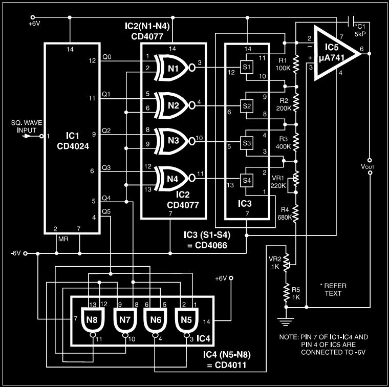
Many electronic devices rely on the shape of signals. Generating square wave signals from sine waves is relatively straightforward, while the reverse process is more challenging. The static square wave-to-sine wave converter circuit can produce an accurate sine wave...
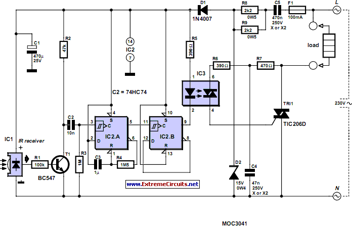
Most homes today have at least a few infrared remote controls, whether for the television, video recorder, stereo, etc. Despite this, many have experienced frustration when the light remains on after settling into a comfortable chair to watch a...
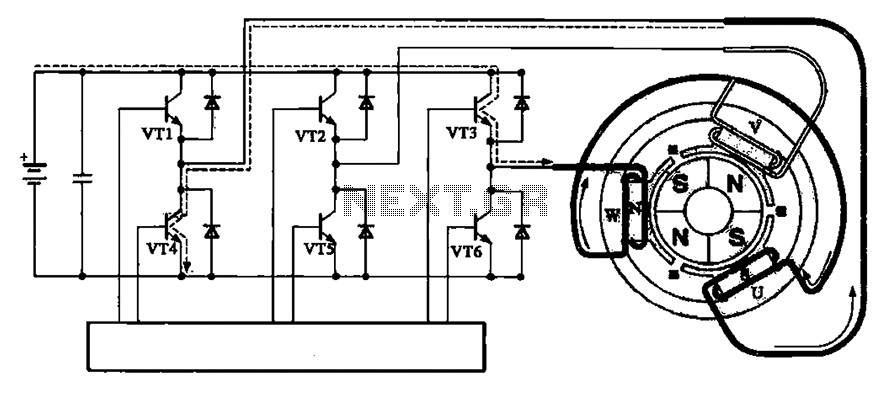
The brushless motor consists of a rotor, a stator, and a drive circuit. The relationship between the brushless motor rotor, stator, and drive circuit is illustrated in the accompanying figure. In the initial state, VT3 and VT4 are conducting,...
The diagram illustrates a human infrared remote sensing lamp circuit. It utilizes the trace infrared heat emitted by humans to control the lamp's operation, allowing it to turn on or off remotely. This human infrared remote sensing lamp features...
At high frequencies, the capacitor Cz can be considered a short circuit (i.e., the resistance of the RPi is negligible). This is illustrated in Figure 4-6 (a) of the apparatus, which corresponds to the equivalent circuit shown in Figure...
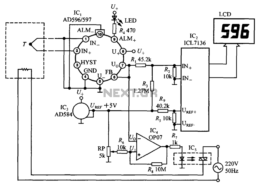
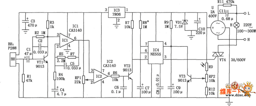
The circuit using AD596/597 forms a temperature measurement and control instrument. In this setup, AD596/597 (IC1) functions as a closed-loop thermocouple signal conditioner. IC2 is a monolithic CMOS 3 1/2 bit A/D converter ICL7136, which can also replace ICL7106,...