
Brushless motor rotor a stator and a drive circuit

The brushless motor operates on the principle of electromagnetic induction, utilizing a rotor and stator configuration to achieve efficient motion without the need for brushes. The rotor, typically composed of permanent magnets, interacts with the stator's electromagnetic fields generated by the drive circuit. The drive circuit comprises a series of transistors (VT1 to VT6) that control the current flow through various coils (W, U, and V), which are arranged in a specific sequence to create rotating magnetic fields.
In the initial state of the motor, VT3 and VT4 are activated, allowing current to flow through coils W and U. This configuration generates a magnetic field that establishes the N and S poles of the stator, facilitating the rotor's movement. The rotor, influenced by this magnetic field, begins to rotate counterclockwise. As the rotor reaches a predetermined speed of 600 RPM, the system transitions by turning on VT1 and VT5. This change modifies the current path, effectively reversing the magnetic polarities at the coils. The result is that the magnetic field at coil U becomes an N-pole while coil V becomes an S-pole, which sustains the rotor's counterclockwise rotation.
The ability to switch the states of the transistors in a precise sequence is crucial for maintaining continuous motion. The drive circuit must be designed to ensure that the transistors operate in a coordinated manner, allowing for smooth transitions and preventing stalling or backtracking of the rotor. This is achieved through the use of a microcontroller or dedicated driver ICs that manage the timing and sequencing of the transistor activations.
Overall, the brushless motor design emphasizes efficiency, reliability, and low maintenance, making it suitable for a variety of applications in robotics, automotive, and industrial automation. The absence of brushes reduces wear and tear, leading to a longer lifespan and improved performance compared to traditional brushed motors. Brushless motor rotor, a stator and a drive circuit Relationship between the brushless motor rotor, a stator and a drive circuit is shown in Fig. The initial state illustrated VT3, VT4 conduction, the power of the positive electrode via a W coil U coil VT3 VT4 a negative electrode to form a loop, loop forming stator poles W N pole, U S coil forming pole, V coil no current. As the role of the stator magnetic field on the rotor poles, the rotor is rotated counterclockwise. When it runs 600, VT1, VT5 from off into a conduction state, the current path is changed, that is a positive power supply VT1 a coil winding U V VT5-- a negative power.
U magnetic coil at the first field becomes N-pole magnetic field at the coil becomes V S, so that the rotor continues to rotate counterclockwise direction (600). After VTl ~ VT6 crystal tube orderly handover can be achieved continuous rotation.
Related Circuits
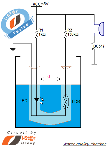
How to measure water purity and test water quality using a simple electronics project. Water purity measurement and water quality analysis can be performed using a water purity checker circuit. This circuit is constructed around a Light Dependent Resistor...
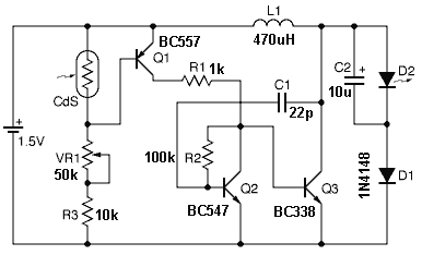
This circuit operates as a 9V DC power source supplying a 555 timer to generate a square wave. The output is then processed through a Half-Wave Series Multiplier (Villard Cascade) to achieve a high voltage DC output. The goal...
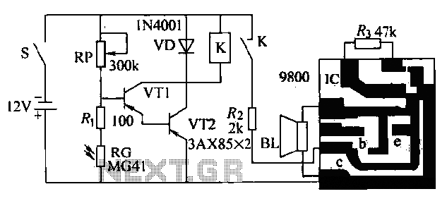
The circuit presented is a second-generation flame alarm for natural gas stoves. After the gas stove is ignited and normal combustion occurs, the power switch S is closed. The photoresistor RG, influenced by the light from the flame, has...
It is essential to draw a circuit using a layout and conventions that are universally recognized. In electronic circuit design, adherence to standardized symbols and layout conventions is crucial for effective communication among engineers and technicians. A well-drawn schematic diagram...
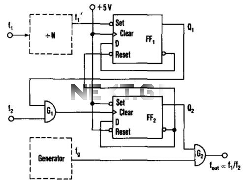
This circuit generates an output frequency that is linearly proportional to the ratio of two input frequencies. Each pulse of the bias frequency will open a switch for a period equal to half of the second input frequency, allowing...
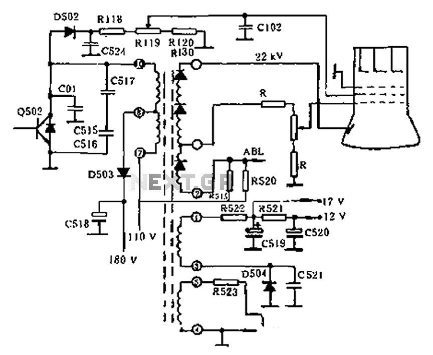
The circuit diagram of the Swallow CS37-2 type color TV illustrates the feeding tube configuration. The filament voltage is supplied by the line flyback transformer, with a current-limiting resistor R523. The accelerating voltage is managed by D502, which rectifies...