
Integrated operational amplifier tone control circuit of a simplified equivalent circuit a

At high frequencies, the behavior of capacitors and resistors within a circuit significantly influences the overall performance. In this context, capacitor Cz is effectively acting as a short circuit, which simplifies the analysis of the circuit by removing the impedance of the RPi. This allows for a clearer understanding of how the remaining components interact under high-frequency conditions.
The maximum lifting capacity formula indicates how the circuit can handle power at elevated frequencies, taking into account the resistances R1, R3, and R2. Each of these resistors contributes to the total impedance experienced by the circuit, and their values must be optimized to achieve desired performance characteristics.
The maximum high-frequency attenuation value provided by the equation shows how the signal strength diminishes as it passes through the circuit. This attenuation is critical in applications where signal integrity is paramount, such as communication systems or high-speed digital circuits.
The assumption that RP2 equals the sum of R1, R3, and twice R2 is essential for simplifying circuit calculations and ensuring accurate modeling of the system's response. This relationship illustrates how the resistive elements work together to define the overall impedance.
Finally, the high-frequency boost corner frequency formula indicates the frequency at which the circuit begins to exhibit significant gain, determined by the resistor R3 and capacitor C2. This frequency is crucial for applications requiring specific bandwidths, as it dictates the operational limits of the circuit. The use of standard units for resistance and capacitance ensures that the calculations can be universally applied and understood within the field of electronics. At high frequencies, q, Cz can be seen as a short circuit (i.e. RPi not present), as shown in Figure 4-6 (a) in the apparatus shown in FIG equivalent to 4-6 (b). Then there are : a high-frequency maximum lifting capacity: A f F (RI + R3 + 2Rz) cuddle 3; maximum high-frequency attenuation value: vc F feet 3/(Ri + R3 ten 2Rz). On two formula assumes: RP2 (Rt ® 3 + 2R2), high-frequency boost corner frequency:, s l/. 7tR3 C2. (Unit: f a ratio, R- fl (Europe), C- F (scared))
Related Circuits
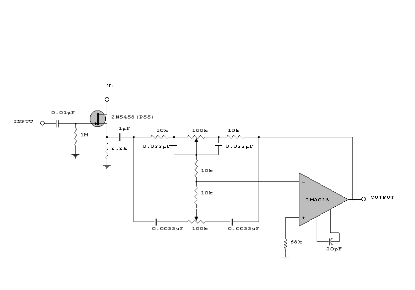
This circuit is a simple series tone control circuit. It utilizes the surgical amplifier LM301A. The JFET 2N3684 provides high input impedance and low noise for the unbuffered operational amplifier, which operates in an equalizer (EQ) configuration. Further details...
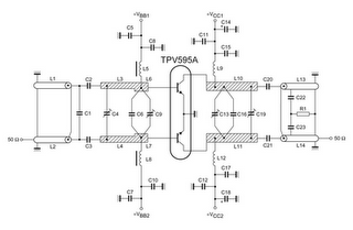
TV RF Power Amplifier 14W. This RF power amplifier operates within the frequency range of 470 - 860 MHz, covering UHF Band IV and V, and delivers an output power of 14 Watts with an input power of 1.5...
The following circuit illustrates a curtain control circuit diagram. This circuit is based on the 555 integrated circuit (IC). Features include a switch for manual control, the IC, and additional components. The curtain control circuit utilizes the 555 timer IC...
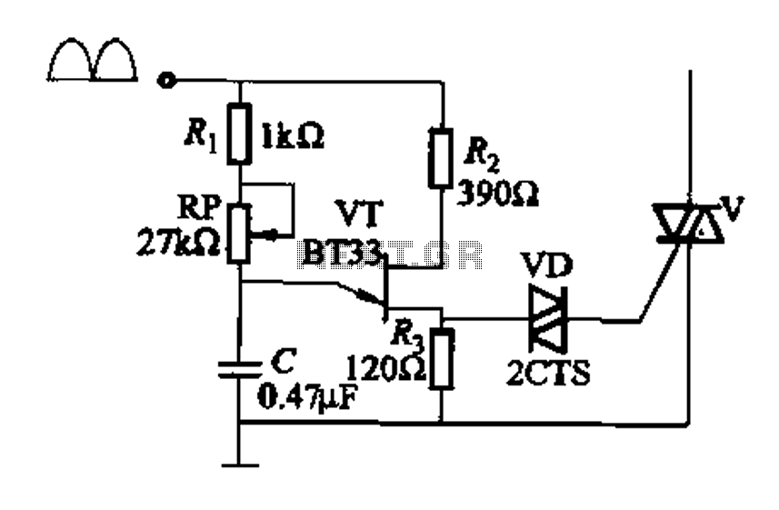
Figure 16-29 (a) illustrates the trigger output through a resistor R2, while Figure 16-29 (b) depicts the integration of a programmable unidirectional transistor (PUT) trigger circuit. The adjustable potentiometer RP can modify the conduction angle of the TRIAC to...
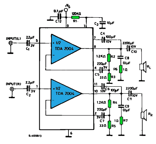
The TDA2004 integrated circuit (IC) is a popular choice among audio electronics enthusiasts due to its affordability and availability. This IC is often utilized in audio amplifier designs because it features two outputs and inputs, making it easy to...
The controller consists of a liquid level sensor, a trigger controller, and a step-down rectifier circuit. The water level detection poles labeled a, b, and c form a bias circuit, functioning as a water level detector with components W1,...