
PTC phase asynchronous motor circuit protection one

The circuit in question integrates two thermal resistors to monitor temperature changes and provide protective and alert functions. The first thermal resistor, Rc, is designed to activate when excessive current or temperature is detected, thereby protecting the circuit from potential damage due to overload conditions. This resistor is typically connected in series with the load, allowing it to sense the thermal rise caused by increased current flow. When the temperature exceeds a predetermined threshold, Rc triggers a mechanism, such as a relay or a circuit breaker, to disconnect the load and prevent overheating.
The second thermal resistor, Rt, is utilized as an alarm system. It is calibrated to respond to different temperature levels than Rc, allowing it to signal when the system is approaching critical operational limits. This can be achieved by connecting Rt to a microcontroller or an alarm circuit that activates a visual or audible alert when the temperature reaches a specific set point. The alarm provides an early warning to operators, enabling timely intervention before any damage occurs.
In terms of configuration, both thermal resistors should be selected based on their resistance-temperature characteristics, ensuring they respond accurately to the expected temperature range of the application. The placement of these resistors within the circuit is crucial; they should be positioned where they can effectively sense the thermal variations without being influenced by external factors. Proper calibration and testing of the thresholds for both Rc and Rt are essential for reliable operation.
Overall, this circuit design effectively combines overload protection with an alarm system, enhancing the safety and reliability of the electronic device it serves. Circuit shown in Figure 4-2. It uses two thermal resistors, a (Rc,) is used as overload protection, another (Rt :) used as an alarm.
Related Circuits
The circuit utilizes 60 individual LEDs to represent the minutes of a clock, along with 12 LEDs to indicate the hours. The power supply and timing circuitry are identical to those described in the previous 28 LED clock circuit....
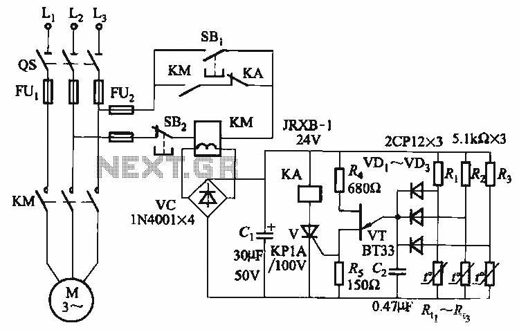
The thyristor control circuit includes a bridge circuit designed to regulate the temperature in the contactor coil KM, along with a secondary winding that functions as a power protection device. It comprises a thermistor (R:., Rt3) and a resistor...
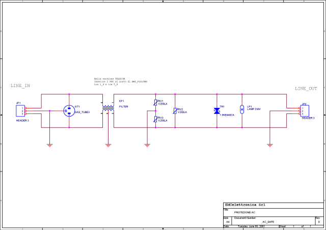
What is a circuit breaker? When is an AC power line filter or a phone line filter necessary? How can a noise filter be designed? Is it possible to create a homemade surge protector? The following circuit protection options...
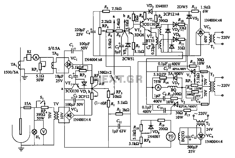
The circuit is illustrated in Figures 16-95 to 16-97. The electrode automatic adjuster demonstrates enhanced performance, featuring a high-accuracy, well-linear current output type bridge. Additionally, it incorporates a differential arc current negative feedback circuit (advanced) that allows for preemptive...
This circuit is a conventional Pierce type oscillator that utilizes a JFET. It operates with fundamental mode crystals and exhibits good performance and reliability when a low noise JFET is employed. The feedback is regulated by the capacitance of...
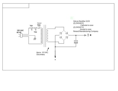
This document outlines a simple circuit diagram for a charger, utilizing a transformer, two SCRs, a capacitor, a heat sink, and a case for assembly. The circuit is designed for charging lead-acid batteries and can function even without the...