
72 LED Clock circuit

The clock circuit is designed to provide a visual representation of time using LEDs, where each LED corresponds to a specific minute or hour. The 60 LEDs for minutes are driven by a series of eight 74HCT164 shift registers, which are configured in a cascaded arrangement. This configuration allows for efficient use of the available outputs, as each shift register can handle a specific number of bits, effectively creating a long chain of outputs that can cycle through the 60 minutes in an hour.
The 74HCT164 is a high-speed CMOS 8-bit shift register that operates on a clock signal, allowing data to be shifted in serially and output in parallel. In this application, the clock signal is derived from the same power supply and timing circuitry used in the previous circuit design, ensuring synchronization and stability. The cascaded arrangement means that the output of one shift register feeds into the input of the next, creating a continuous loop that recirculates a single bit through all 60 stages.
The 12 LEDs indicating hours are likely driven by a separate mechanism, which may involve a similar or different set of shift registers or a dedicated counter circuit. This allows for a clear distinction between the minute and hour indicators, providing a comprehensive visual representation of the current time. The entire circuit is designed to be efficient and straightforward, making it suitable for applications where a simple yet effective time display is required.In the circuit, 60 individual LEDs are used to indicate the minutes of a clock and 12 LEDs indicate hours. The power supply and time base circuitry is the same as described in the 28 LED clock circuit above. The minutes section of the clock is comprised of eight 74HCT164 shift registers cascaded so that a single bit can be recirculated through the 60 stages indicating the appropriate minute of the hour..
🔗 External reference
Related Circuits
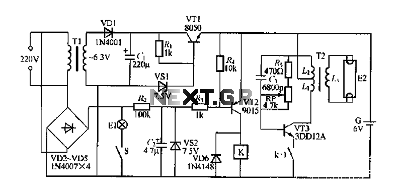
FIG. 284 illustrates a practical emergency power lighting system that activates automatically in the event of a sudden power outage. The fluorescent lights serve as emergency lighting. If the primary illumination lamp is turned off due to a power...

This circuit creates an impressive display of magnetism by suspending a small metal object in mid-air. Utilizing an electromagnet, a photo sensor, and a closed-loop control system, lightweight metal objects can be levitated just beneath the magnet, enclosed in...

The circuit is designed to regulate a dual power supply that provides +12V and -12V from the AC mains. Such a power supply is an essential tool for an electronic hobbyist's workbench. The schematic of the circuit includes components...
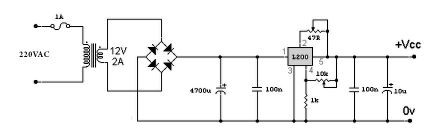
A variable power supply based on the L200 IC, where the output voltage is controlled by a 10K variable resistor. The output voltage ranges from approximately 3 to 15 volts, with a current output ranging from a minimum of...
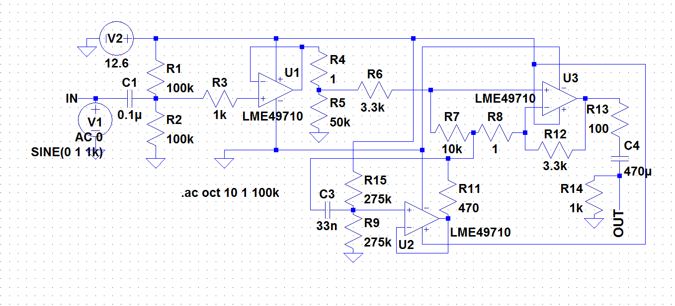
A circuit was required to function as a bass boost. The design was adapted from a circuit by ESP Sound, focusing solely on the frequency range of 35-150 Hz. The bass boost circuit, as adapted from the original design, primarily...

The circuit is illustrated in Figures 16-95 to 16-97. The electrode automatic adjuster demonstrates enhanced performance, featuring a high-accuracy, well-linear current output type bridge. Additionally, it incorporates a differential arc current negative feedback circuit (advanced) that allows for preemptive...