
Explanation Regarding Audio Mixer Circuits

The inquiry indicates a desire to learn and engage with the community on topics related to DIY electronic circuits. For individuals in similar situations, it is recommended to start with foundational concepts in electronics, such as understanding basic components like resistors, capacitors, diodes, and transistors.
A basic electronic circuit can be constructed using a battery, a resistor, and an LED (light-emitting diode). In this simple circuit, the battery serves as the power source, providing the necessary voltage. The resistor is used to limit the current flowing through the LED, preventing it from burning out due to excessive current.
The schematic representation of this circuit would include the battery symbol, a resistor symbol, and the LED symbol, with appropriate connections made to indicate the flow of current. The positive terminal of the battery connects to one end of the resistor, while the other end of the resistor connects to the anode of the LED. The cathode of the LED then connects back to the negative terminal of the battery, completing the circuit.
This introductory circuit serves as an excellent starting point for understanding more complex electronic designs. As knowledge and skills develop, one can explore additional components and circuit configurations, gradually building a more comprehensive understanding of electronics. Engaging with the forum by asking questions and sharing projects can further enhance the learning experience.Hi all, I am very new to this forum as well as DIY electronic circuits. I am not an electrical engineering student nor I have sufficient background (I .. 🔗 External reference
Related Circuits
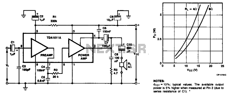
The monolithic integrated audio amplifier circuit is specifically designed for portable radio and recorder applications, delivering up to 4 W into a 4-ohm load impedance. The power output is close to 6 watts RMS. The monolithic integrated audio amplifier circuit...
The audio ground is completely isolated from the digital ground. The top copper layer is utilized as a shield for both the audio and digital ground, which aids in preventing the audio section from picking up noise from the...
The circuit was intentionally designed without integrated circuits (ICs) and follows a traditional approach to achieve favorable harmonic distortion characteristics while avoiding the use of hard-to-find components. The amplifier can be powered conveniently using a 12V wall plug-in adapter....
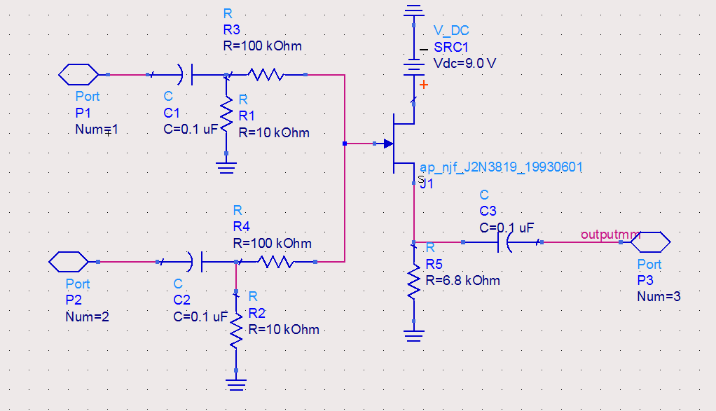
The circuit utilized was primarily designed for audio mixing, featuring inputs from both a triangular wave generator and a noise generator. These signals are processed through an audio mixer to create the final output wave. This audio mixing circuit integrates...
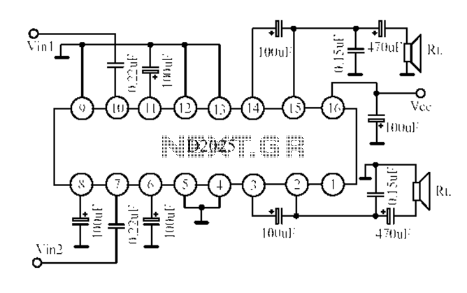
The D2025 is a dual audio power amplifier circuit designed as a stereo audio power amplifier integrated circuit. It comes in a DIP16 package and is applicable for various portable devices, such as tape recorders or portable stereo systems....
Low distortion bass and treble control for an amplifier. Circuit diagram. Electronics project. The low distortion bass and treble control circuit is designed to enhance the audio quality of an amplifier by allowing precise adjustments to the low and high-frequency...