
Rain alarm schematic circuit diagram

The described circuit functions as a rain detection and alarm system, utilizing a simple yet effective design. The primary components include a probe, which is sensitive to moisture, and a resistor that forms part of the detection mechanism. When raindrops fall on the probe, they create a conductive path between the two leads, effectively completing the circuit.
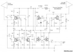
The audio circuit is designed to generate an audible alert when the probe detects moisture. This is achieved through the integration of a capacitor, as depicted in Figure 2, which may serve to filter or stabilize the signal generated by the probe. The capacitor allows for the proper functioning of the audio output, ensuring that the sound produced is clear and effective in alerting users to the presence of rain.
In addition to its primary function as a rain alarm, the circuit can be adapted for various applications requiring water detection. By modifying component values or configurations, the design can be tailored to suit different environments or sensitivity requirements. This flexibility makes it a valuable solution for diverse water alarm needs, ranging from outdoor rain detection to indoor flood monitoring. Overall, the circuit provides an efficient and reliable method for water detection and alarm signaling.FIG. 1 is a circuit diagram of it, it is in the audio circuit from the resistance between the two leads to a probe to rain alarm. Fig. 2 with CCL to make a probe connected to t he audio circuit, when the rain drops on the probe, the circuit is turned on, the sound will be issued. The alarm can also be used as a variety of water alarm device. Figure 1 Figure 2
Related Circuits
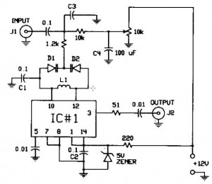
The FM modulator circuit, which utilizes frequency modulation, is constructed with a Motorola MC1648P oscillator. It employs two varactors, specifically Motorola MV-209, to achieve frequency modulation of the oscillator. A 5000 Ω potentiometer is incorporated to bias the varactors...

This project presents numerous practical applications in security and alarm systems for homes, shops, and vehicles. The circuit is highly sensitive and can be configured to either reset automatically or remain triggered until manually reset after an alarm. It...
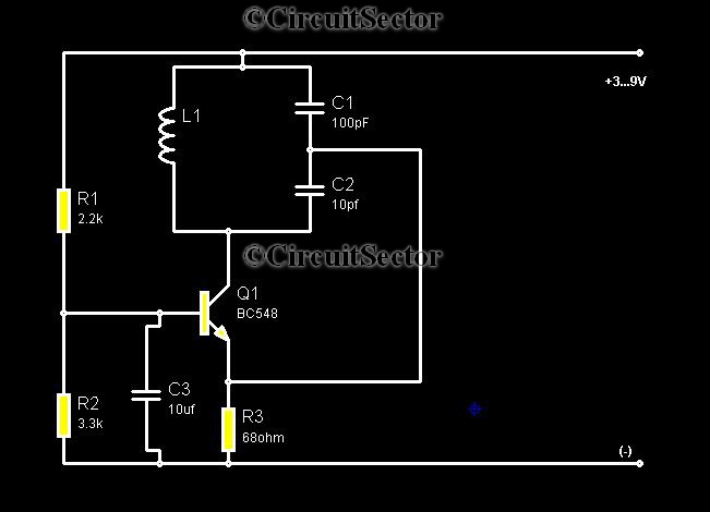
Metal detectors are typically complex devices that often incorporate expensive components, making DIY metal detector circuits uncommon. However, this metal detector hobby circuit can be built using only a few components, such as a BC548 transistor and a standard...
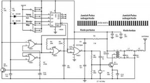
The following circuit illustrates a schematic diagram for a remote control toy car. Features: it does not affect the performance of the original design. The remote control toy car schematic circuit diagram typically consists of several key components that work...
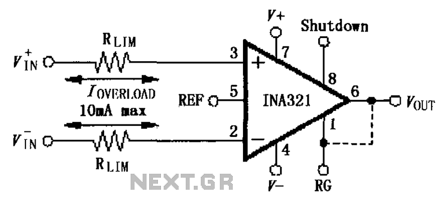
The input current protection circuit for the INA321/322 is illustrated. The INA321/322 features input terminal electrostatic discharge (ESD) protection diodes that become conductive when the input voltage exceeds the supply voltage by 500mV. The protection diodes will conduct, and...
The PT2399 digital echo circuit schematic is an electronic design that utilizes the PT2399 integrated circuit (IC) for audio applications. This digital echo processor, based on CMOS technology, incorporates both analog-to-digital conversion (ADC) and digital-to-analog conversion (DAC) processes for...