
Remote Control Toy Car Schematic

The remote control toy car schematic circuit diagram typically consists of several key components that work together to facilitate wireless control and operation. The main components include a transmitter, receiver, motor driver, and power supply.
The transmitter is responsible for sending control signals to the receiver located in the toy car. This is often achieved using a radio frequency (RF) module or an infrared (IR) transmitter, depending on the design specifications. The transmitter may include control switches or joysticks that allow the user to dictate the car's movements, such as forward, backward, left, and right.
The receiver, which is integrated into the toy car, decodes the signals received from the transmitter. It is typically paired with a microcontroller or a dedicated RF receiver module that interprets these signals and converts them into actionable commands for the motor driver.
The motor driver is a crucial component that interfaces between the receiver and the toy car's motors. It amplifies the control signals from the receiver to drive the motors effectively. Depending on the design, the motor driver may be a simple H-bridge circuit that allows for bidirectional control of the motors, enabling the car to move in both directions.
Power supply considerations are also essential in this circuit design. The toy car generally operates on a battery, which must provide sufficient voltage and current to power both the motors and the electronic components. Voltage regulators may be employed to ensure that the various components receive stable operating voltages.
In summary, the remote control toy car schematic circuit diagram integrates a transmitter, receiver, motor driver, and power supply, ensuring seamless operation while maintaining the original performance characteristics of the toy car.The following circuit shows about? Remote Control Toy Car Schematic Circuit Diagram. Features: does not impose on the performance of the original . 🔗 External reference
Related Circuits
This circuit employs the widely used and easily accessible LM3914 integrated circuit (IC). The LM3914 is straightforward to operate, does not require external voltage regulators due to its built-in voltage regulation, and can be powered by a variety of...
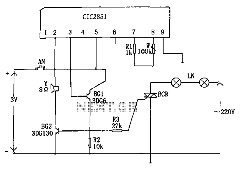
The non-contact lantern control circuit includes an integrated music IC (CIC2851), transistors (BG1 and BG2), a thyristor (SCR), and other components. When the switch is pressed (AN), the CIC2851 is activated, causing the output terminal (pin 3) to emit...
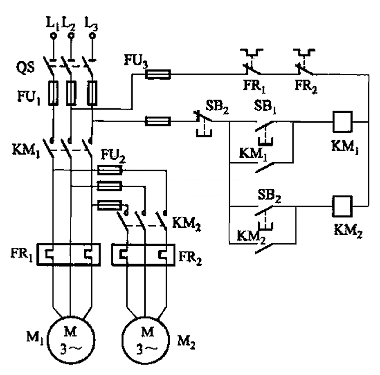
The circuit illustrated in Figure 3-83 demonstrates that the contactor KMi is activated only after it is pulled, which indicates that the motor Mi has started for the first time. Following this, the contactor KM2 is then activated, indicating...
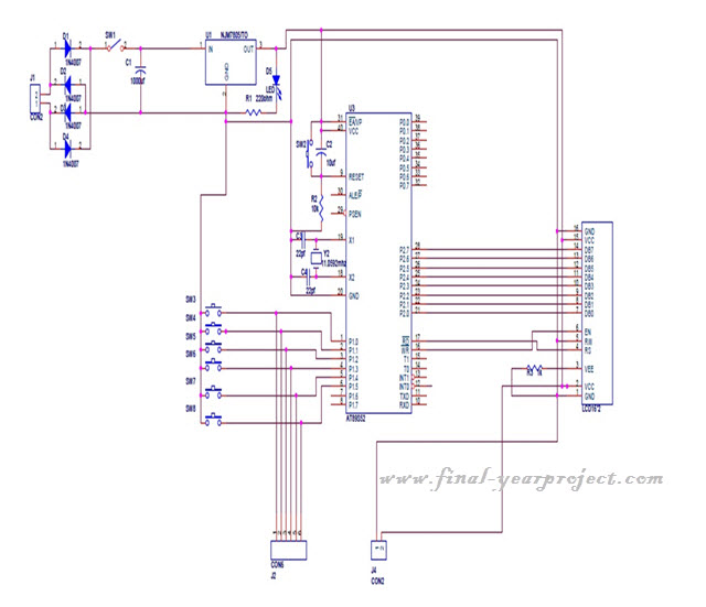
This project is a microcontroller-based college automation system aimed at addressing the challenges faced in educational institutions. It replaces the conventional notice board with an automated device that allows users to both hear and read the information being announced...
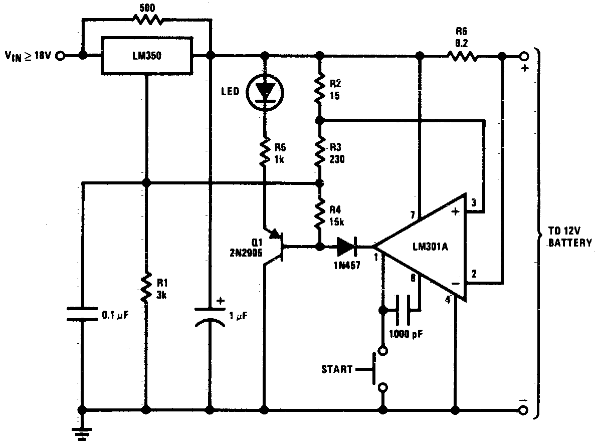
DC 12V Battery Charger Circuit Diagram. This circuit is a high-performance charger for gelled electrolyte lead-acid batteries. The DC 12V battery charger circuit is designed to efficiently charge gelled electrolyte lead-acid batteries, which are commonly used in various applications due...
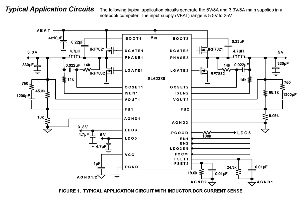
The ISL62386 controller generates supply voltages for battery-powered systems. It features two pulse-width modulation (PWM) controllers that are adjustable from 0.6V to 5.5V, along with two linear regulators, LDO5 and LDO3, which provide fixed outputs of 5V and 3.3V,...