
Blackout emergency lights circuit 4

E1 also by the voltage across R, step-down current limiting and VS2 regulator, the DC output voltage by R. 7 SV Was added to a symbol VT2 PNP base, so its reverse bias is turned off, the relay is still action.
Meanwhile, AC transformer T] Yoshitsune Buck, Vn1 rectifier Simple constant pressure and composition of the VS1 and VT1 to the battery charging circuit C is charged. If at this time a sudden power failure, stop the output VT1 off the charging current, and c. The stored charge through R, E1 and S discharge quickly, this time (can through Vl, 2 emitter, R, R., El and S constituting the discharge circuit, so quickly make VT2 conduction, the relay K was electric suction units, contact k 1 is closed, the inductor three-point oscillator powered by the VT3 composed of start-up, the oscillation frequency of about iookHz, this oscillating current after T2 fluorescent lamp E2 rapidly boost electric lights, for emergency according to Ming, VT1 to 8050 Journal of power silicon tube, mouth 100; Vl, 2 with 9 () 15 criminal silicon tube to seek mouth OO: VT3 available 3DD12A, 3DD15A type silicon and other low-frequency high-power tube, should gizzards 25.
installation for installation 70nun 40mm mm aluminum cooling plate .Tl of 22 () V, 6 3V, 5VA small, high quality power transformers, requiring long power/heat .r2 need white system: the use of ferrite O 22mm in diameter Hugh magnetic tank, L. O In.m with high strength enameled wire wound on the skeleton level 9 turns/, with O 3mni enameled high strength at around 8 L.
outer flat turns, L. with 40. 2rnm l Island strength enameled wire skeleton chaos around 200 turns. in between L. and L. v should be less padded insulation paper (paper with desirable} U insulating paper container) breakdown prevent the occurrence of ignition phenomena in use and dip varnish at the processing, to be painted through the rear opening T .K state officials with JZC-22F, DC6V power in a small electromagnetic relay .E2 can use 8w fluorescent tubes .G as 6V, 4Ah battery maintenance-free phthalocyanine. inductance three-point oscillator is required to be adjusted, Dong RP can change the brightness of the light emitting tube E2 discretion if the lamp.
disobedient does not shine, the circuit can not oscillate cho coil r. or /: two-thread reversed as long as I. of. two thread swap about to bite to r,
Related Circuits
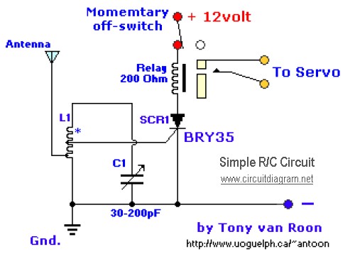
The diagram illustrates a straightforward and efficient receiver designed for activating garage doors, starter motors, alarms, warning systems, and various other applications. The silicon-controlled rectifier (SCR) utilized in this circuit features an exceptionally low trigger current of 30 µA,...
The circuit has been designed for telephone apparatus to indicate an incoming call as it rings using an LED for visual indication. BC550, an NPN general-purpose transistor, is utilized in the design. The circuit operates by detecting the ringing voltage...
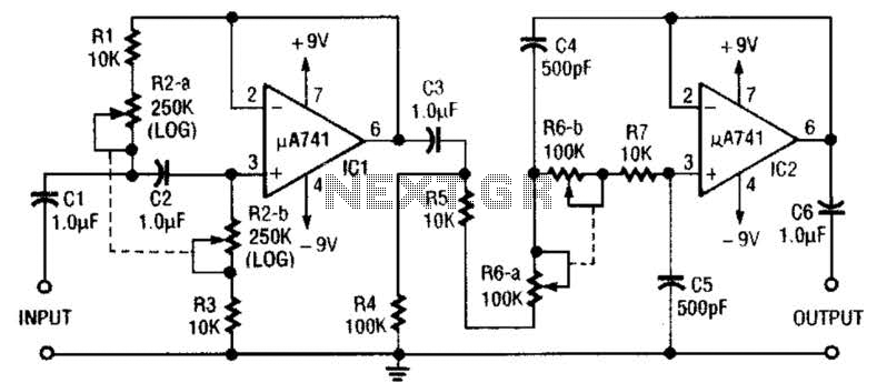
This circuit is a variable audio bandpass filter that features a low cutoff adjustable from approximately 25 Hz to 700 Hz and a high cutoff adjustable from 2.5 kHz to over 20 kHz. The roll-off is set at 12...

This is a Variable Voltage Regulator Circuit built using the LM317T integrated circuit (IC). The LM317T is an adjustable three-terminal positive voltage regulator capable of supplying more than 1.5 amps over an output range of 1.25 to 37 volts....
A simple USB FM transmitter that can be used to play audio files from an MP3 player or computer on a standard VHF FM radio by connecting it to a USB port. The circuit does not require any coils...
To enhance usability during nighttime, the receiver features a scale with bias lighting, and the surface behind the scale is coated with a fluorescent material. To activate the scale illumination, press button 3. Radio programs can be listened to...