
Variable Bandpass Audio Filter Circuit

The described variable audio bandpass filter circuit utilizes two ganged potentiometers, R2-a-b and R6-a-b, to allow for precise control over the frequency response. The low cutoff frequency range from 25 Hz to 700 Hz is achieved by adjusting R2, which effectively determines the lower limit of the audio spectrum that will be allowed to pass through the filter. This is particularly useful in audio applications where it is necessary to eliminate low-frequency noise or rumble while preserving the desired audio signals.
Similarly, R6-a-b is responsible for adjusting the high cutoff frequency, which ranges from 2.5 kHz to over 20 kHz. This adjustment enables the filter to selectively allow higher frequency audio signals to pass while attenuating frequencies above the set threshold. The 12 dB/octave roll-off characteristic on both ends ensures a gradual decline in signal amplitude outside the designated frequency bands, preventing abrupt changes that could introduce distortion or unwanted artifacts into the audio signal.
In practical applications, this bandpass filter can be employed in various audio processing scenarios, such as in equalizers, synthesizers, and sound reinforcement systems, where control over specific frequency ranges is essential. The use of ganged potentiometers allows for simultaneous adjustment of both cutoff frequencies, maintaining the desired bandwidth of the filter while ensuring ease of use for the operator. The design can be further enhanced by incorporating additional components, such as operational amplifiers for buffering and gain control, or capacitors for fine-tuning the filter characteristics. Overall, this circuit represents a versatile solution for audio signal processing, enabling tailored frequency response for diverse applications. This circuit is a variable audio bandpass filter that has a low cutoff variable from about 25 Hz to 700 Hz and a high cutoff variable from 2.5 kHz to over 20 kHz. Rolloff is 12 dB/octave on both high and low ends. R2-a-b and R6-a-b are ganged potentiometers for setting lower and upper cutoff frequencies, respectively.
Related Circuits
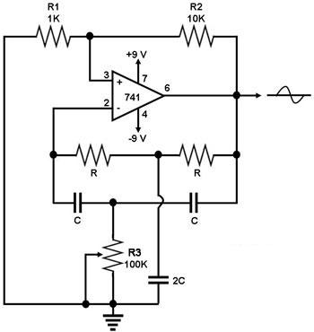
This circuit generates a sine wave using a single operational amplifier (741). The feedback loop of the op-amp includes a twin-T filter connected between its output and inverting input. Positive feedback for oscillation is provided by resistor R2. The...
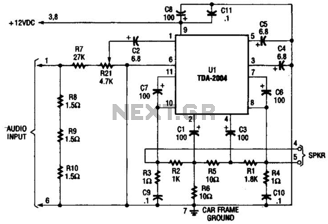
Only one channel of this circuit is shown. The other is practically identical. The input to the circuit, taken from the speaker output of a car radio, is divided into two paths. In one path, a high-power divider network...
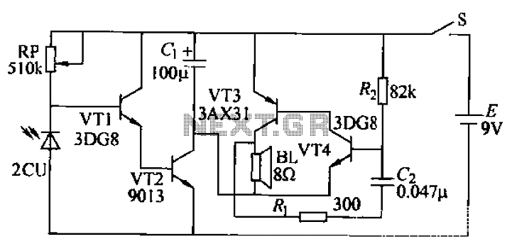
Boiling water or cooking with a gas stove can sometimes lead to the fire being extinguished due to water spills, which can result in a significant gas overflow and pose a risk of poisoning. This example describes a stall...
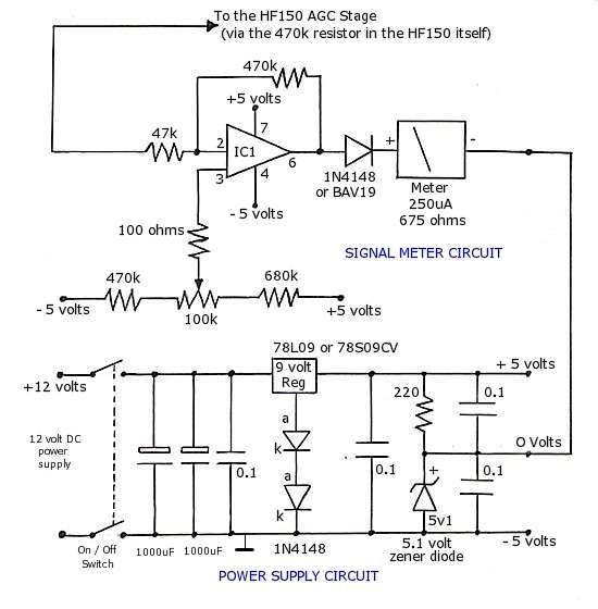
The operational amplifier (op-amp) used in the signal meter circuit is the TL061. The LF351 can also be used interchangeably, as it has the same pin layout. For those using a TL062 or similar models, the differing pin configurations...
This active antenna schematic can be used to frequency range from 10 KHz to 100 MHz. The length of the Antenna can be between 0.5 to 1 meter long. The power consumption is 20-30mA. More: Use the shortest possible...
This circuit serves as a decorative element or indicator, featuring adjustable flashing or dancing speeds of LEDs and the ability to create various light patterns. It consists of two astable multivibrators: one formed by transistors T1 and T2, and...