
Test Bench Power Supply Schematic

The power supply circuit in question is designed to convert the 120 volts AC from the mains into a usable DC voltage for various electronic applications. The circuit typically includes a transformer, rectifier, filter, and voltage regulator components.
1. **Transformer**: The transformer steps down the 120 volts AC to a lower voltage suitable for the intended application. It also provides electrical isolation from the mains, enhancing safety.
2. **Rectifier**: Following the transformer, a rectifier circuit is employed, commonly using diodes to convert the AC voltage to pulsating DC. A full-wave bridge rectifier configuration is often utilized for better efficiency and smoother output.
3. **Filter**: The output from the rectifier is then passed through a filter, usually consisting of capacitors, to smooth out the pulsating DC into a more constant voltage. This stage is crucial for reducing ripple voltage, ensuring that the output is stable and suitable for powering sensitive electronic devices.
4. **Voltage Regulator**: Finally, a voltage regulator may be included to maintain a constant output voltage despite variations in input voltage or load conditions. This component is essential for applications where precise voltage levels are critical.
Safety precautions must be observed when working with high voltages. Proper insulation, fuses, and circuit protection devices should be implemented to prevent electrical hazards. Additionally, all components should be rated for the expected voltage and current levels to ensure reliable operation and prevent component failure.
This power supply circuit is commonly used in various applications, including powering microcontrollers, sensors, or other electronic devices that require a stable DC voltage.This power supply circuit uses 120 volts household mains and should only be attempted by someone that has the knowledge and skills to safely construct such a project. Otherwise personal injury and or property damage could result. 🔗 External reference
Related Circuits
The telephone ring generator shown below generates the needed high voltage from a simple switching mode power supply (SMPS) which employs a CMOS Schmitt Trigger square wave oscillator, 10 mH inductor, high voltage switching transistor (TIP47 or other high...
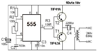
This 12V power inverter circuit can be utilized to power small devices that require 240 volts. It is particularly advantageous for operating 240-volt appliances using a 12-volt car battery. Unlike typical feedback oscillator inverters, this design employs a 555...
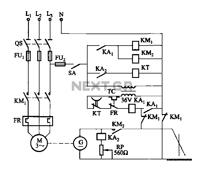
The DC arc welding machine is connected to the secondary load path of the power circuit as illustrated in the figure. This circuit is designed for use during extended downtime, approximately lasting a few minutes, and is not suitable...
This chapter provides detailed schematics of various power supplies suitable for use with common Ar/Kr ion tubes available to hobbyists in the surplus market. Included are examples of commercial designs (Omnichrome 150R and 532 head, Lexel 88 and head)...
This circuit is a small +5V power supply, which is useful when experimenting with digital electronics. Small inexpensive wall transformers with variable output voltage are available from any electronics shop and supermarket. Those transformers are easily available, but usually...
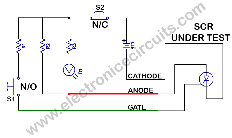
SCR Tester Circuit. The device under test, cathode, anode, and gate are connected to the unit's cathode, anode, and gate terminals. The SCR tester circuit is designed to evaluate the functionality of Silicon Controlled Rectifiers (SCRs) by facilitating connections to...