
Power supply monitor

The described circuit employs a tricolor LED display, which serves as a visual indicator for voltage levels in a monitored system. The circuit includes voltage reference points, typically set using potentiometers, to define the upper and lower voltage thresholds. These reference points are compared against the monitored voltage via a microcontroller or comparator circuit.
The green LED indicates normal operating conditions, lighting up when the monitored voltage is within the defined range. The red LED activates when the voltage exceeds the upper limit, signaling a critical condition that requires immediate attention. Conversely, the yellow LED serves as an alert for voltages that fall below the lower limit, indicating potential system failure or malfunction.
The circuit's design allows for flexibility in application; it can be configured to monitor voltage levels for a single power supply or to compare two different voltages. In the latter case, additional components such as differential amplifiers may be utilized to accurately measure the voltage difference. The alarm system can be implemented using simple buzzer circuits or more sophisticated sound modules, depending on the required alerting mechanism.
For remote monitoring capabilities, the circuit can incorporate wireless transmission modules, such as Wi-Fi or Bluetooth, enabling real-time feedback to an operator's device. This feature enhances system oversight, especially in industrial environments where immediate responses to voltage fluctuations are crucial.
Overall, the circuit's ability to operate without an external power supply, combined with its adaptability for various monitoring scenarios, makes it a versatile tool in electronic applications.This circuit uses a tricolor LED display to indicate acceptable and unacceptable output voltages. One to set the upper voltage limit, the other, the lower voltage limit. When the monitored voltage is above the set maximum, the LED display turns red. Yellow turns On for voltages below the set minimum, and green turns on for voltages between the high and the low settings. The circuit does not need a separate power supply. It is powered by the voltage it monitors. The circuit can be adapted to monitor voltage differences between two power supplies. Should the monitored voltages differ by more than a set value, a visual or an audible alarm would warn the operator about the difference. The circuit can also be modified for remote monitoring and the use of a separate power supply.
Related Circuits
This line voltage power controller connects a DC control voltage or microprocessor logic output to an AC load. By adding a filter capacitor to the input resistors, the circuit can be controlled by a duty-cycle modulated square wave with...
The circuit diagram illustrates a voltage regulator designed from discrete components to meet specific voltage requirements. It provides two sets of component values for output voltages of 6.3 V (upper) and 12.6 V (lower). The components used include BC547...
The ADM1066 from ADI Company is a monitoring device designed to manage various configurable sequencing applications. It features 12 ADCs and 6 8-bit DACs with a voltage output precision exceeding 0.5% at 25 degrees Celsius. This device is primarily...
This document presents a schematic diagram of an electret microphone pre-amplifier utilizing the LMV721 operational amplifier. The LMV721 is chosen for its low noise and low power characteristics. The electret microphone pre-amplifier circuit is designed to amplify the weak audio...
High-voltage power supply circuit for fluorescent light power supply. Refer to that page for an explanation of the related circuit diagram. The high-voltage power supply circuit designed for fluorescent lights typically consists of several key components that work together to...
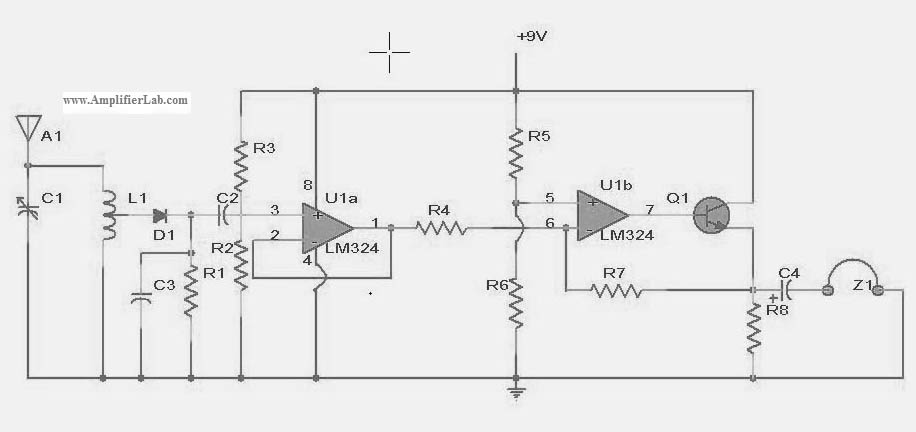
The following circuit illustrates a power amplifier electronic circuit, specifically a tube audio RF amplifier circuit diagram. This circuit is based on the LM324 integrated circuit. The power amplifier circuit utilizing the LM324 operational amplifier is designed to enhance audio...