
0-28 Volt 6A regulated variable power supply circuit with 7815 and two 2n3055

The described power supply circuit is a versatile solution for applications requiring adjustable voltage and current. The use of two 2N3055 transistors in a push-pull configuration enhances the output current capability, making it suitable for powering devices that demand higher current levels. The 7815 voltage regulator serves as a fundamental component for maintaining a stable output voltage under varying load conditions, while the fuses provide essential protection against overcurrent scenarios, ensuring the longevity and reliability of the power supply.
The rectification stage is crucial, as it converts the AC voltage from the transformer into a stable DC voltage. The calculated rectified voltage of approximately 42.30 volts necessitates the use of capacitors rated for at least 50 volts to prevent breakdown and ensure safe operation. The inclusion of diodes in the output stage not only aids in achieving the desired voltage range but also protects the transistors from potential damage due to excessive voltage.
The adjustable output voltage, facilitated by the potentiometer P1, allows users to fine-tune the voltage to meet specific requirements, making this power supply suitable for various electronic projects. The current limiting feature provided by potentiometer P2 is particularly beneficial in preventing damage to both the power supply and connected loads, as it allows users to set a safe operating current.
In summary, this power supply circuit is designed with both functionality and safety in mind, providing a robust solution for a wide range of electronic applications. The careful selection of components and design considerations ensures reliable operation, making it an excellent choice for hobbyists and professionals alike.This is definitely an simple to create power supply which has reliable, clear and regulator 0 to 28 Volt 6/8 Ampere output voltage. By using two 2N3055 transistor, you`ll get two times the amount of electric current. Although the 7815 power regulator is going to kick in on brief circuit, overload and thermal overheating, the fuses within the prima
ry section of the transformer and also the fuse F2 in the output will protected your power supply. The rectified voltage of: 30 volt x SQR2 = 30 x 1. 41 = 42. 30 volt measured on C1. So all capacitors ought to be rated at 50 volts. Caution: 42 volt is the voltage that might be around the output if one of the transistors ought to blow. P1 allows you to `regulate` the output voltage to anything between 0 and 28 volts. The LM317 lowest voltage is 1. 2 volt. To have a zero voltage around the output I`ve put 3 diodes D7, D8 and D9 on the output of the LM317 to the base of the 2N3055 transistors.
The LM317 optimum output voltage is 30 volts, but applying the diodes D7, D8 & D9 the output voltage is approx 30v - (3x 0. 6v) = 28. 2volt. P2 will certainly let you to set the limit of the optimum available electric current at the output +Vcc.
When using a 100 Ohm / 1 watt variable resistor the current is limited to approx. 3 Amps @ 47 Ohm and +- 1 Amp @ 100 Ohms. 🔗 External reference
Related Circuits
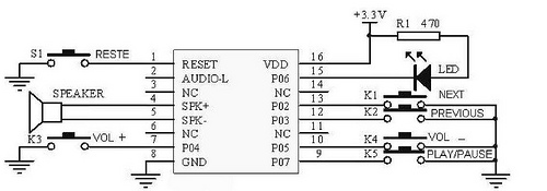
This tutorial focuses on the MP3 mode of the WTV020SD-16P module. With this straightforward circuit, AD4 format music files can be played. A video demonstration of this simple project is available at the end of the article. The project...
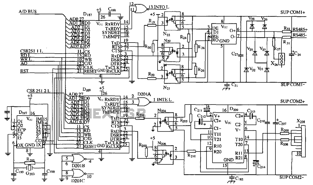
As shown in the figure, D187 is a universal asynchronous receiver-transmitter (UART). Its RX/TX signals are received through optocouplers N21, N22, and N29, facilitating RS-485 communication. The interface receiver/transmitter D28 and microprocessor D211 are completely optically isolated. D197 serves...
The LED flasher circuits operate on a single 1.5-volt battery. The circuit on the upper right utilizes the popular LM3909 LED flasher IC and requires only a timing capacitor and an LED. The LED flasher circuit using the LM3909 integrated...

The application involves observing the light pulse emerging from a thick specimen after transillumination by a laser pulse. Pulses derived from the laser source are amplified using a Video Amplifier LM733. The reference level is set to 1 V...
The thermistor utilized has a resistance of 15k ohms at 25 degrees Celsius and 45k ohms at 0 degrees Celsius. A suitable bead-type thermistor can be sourced from the Maplin catalogue. The inclusion of a 100k potentiometer enables this...
Many battery-powered devices utilize two AA alkaline cells. Often, the user is unaware of when to replace the batteries until the device ceases to operate. The hobby circuit described below can be connected to a 3V battery, providing a...