
Photomultiplier output-gating circuit

The circuit described is designed to observe light pulses generated from a thick specimen illuminated by a laser pulse through transillumination. The system employs a laser source that emits pulses at a frequency of 500 Hz. The initial light pulses produced by the laser are weak and require amplification to be effectively processed. A Video Amplifier LM733 is used for this amplification, ensuring that the signal is strong enough for subsequent processing.
To manage the signal effectively, a comparator LM710 is utilized. It is configured with a reference level set at 1 V, which serves as a threshold for triggering the next stage of the circuit. The output from the comparator generates trigger pulses that are fed into a monostable multivibrator, specifically the 74121 model. This component is critical in generating a defined output pulse in response to the trigger input, which is essential for timing and synchronization in the overall system.
The component values specified in the circuit are crucial for determining the behavior of the monostable multivibrator. The resistors and capacitors, R1 = 33 kΩ, C1 = 22 pF for the first stage and R2 = 33 kΩ, C2 = 68 nF for the second stage, are selected to ensure that the pulse width (t_w) generated by the monostable multivibrator is appropriate for the application. The pulse width can be calculated using the formula t_w = 0.7 RC, highlighting the relationship between resistance, capacitance, and the resulting pulse duration.
Additionally, R3 and C3 form a high-pass filter in the circuit. This filter serves to eliminate low-frequency noise and allows only the higher frequency components of the signal to pass through, further refining the output signal. The design emphasizes the use of low-cost components, which is advantageous for practical applications where budget constraints are a consideration, while still achieving moderate response times necessary for effective pulse extraction. This approach ensures a balance between performance and cost, making the circuit suitable for various experimental setups in optical and photonic applications.The application involves observing the light pulse emerging from a thick specimen after transillumination by a laser pulse. Pulses derived from the laser source are amplified using a Video Amplifier LM733. The reference level is set to 1 V in the comparator LM 710, to provide the necessary trigger pulses for the monostable multivibrator 74121.
The laser pulses have a repetition frequency of 500 Hz and suitable values are as below: Rl = 33 k ohm, Cl = 22 pF R2 = 33 k ohm, C2 = 68 nF. The pulse width for each monostable is approximately given by tw = 0.7 RC. R3 and C3 is a high pass filter. The method therefore permits the use of low cost components having moderate response times for extracting the pulse of interest.
Related Circuits
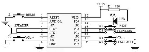
This tutorial focuses on the MP3 mode of the WTV020SD-16P module. With this straightforward circuit, AD4 format music files can be played. A video demonstration of this simple project is available at the end of the article. The project...
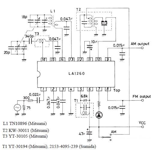
A very simple FM IF MW radio receiver circuit can be designed using the LA1260 IC manufactured by Sanyo Semiconductor. This FM IF MW radio receiver circuit schematic shows that the LA1260 IC can be utilized in AM and...

This device enables two computers to share a single USB printer or other USB devices such as an external flash drive, memory card reader, or scanner. A rotary switch is used to select the PC that will connect to...

The following circuit illustrates a Slave Flash Light Control Circuit Diagram. Features include a 68 mH inductor, which provides an automatic trigger for the secondary flash light. The Slave Flash Light Control Circuit is designed to enhance the functionality of...

The LR inputs are summed, processed, and then drive a comparator. This comparator detects levels and generates transitions when audio inputs exceed or fall below predetermined thresholds. The frequency of these transitions, which correspond to rapid volume changes, is...
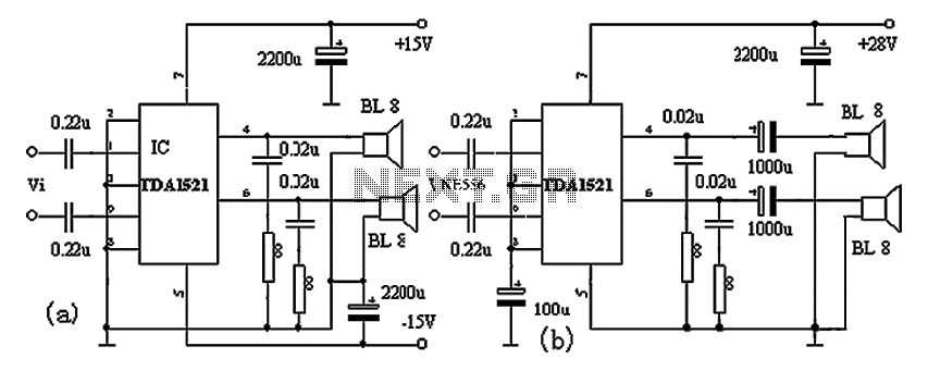
The TDA1521A amplifier circuit is designed for high-fidelity applications with minimal external components. It is suitable for powering Walkman devices or transforming low-powered computer speakers. The TDA1521A comes in a nine-pin single in-line plastic package and offers output power...