
3v low battery voltage flasher

The described circuit operates as a battery voltage monitor and alert system, specifically designed for devices powered by two AA alkaline cells. The voltage detector IC continuously monitors the battery voltage levels, ensuring that users are alerted before the battery reaches a critically low state. The selection of a voltage threshold at approximately 2.4 volts is strategic, as it provides a balance between maximizing battery life and ensuring reliable operation of the connected device.
In standby mode, the circuit's low power consumption of 1 µA ensures minimal impact on battery life, making it suitable for long-term applications. When the voltage drops below the specified threshold, the voltage detector's open-drain output transitions to a low state, activating the oscillator circuit. This oscillator is configured using two transistors, which work together to create a pulsing signal that drives the LED. The brief current pulses of 2 ms are sufficient to produce a visible flash from the LED without drawing excessive current, which would otherwise accelerate battery depletion.
The implementation of this circuit is straightforward, requiring minimal components and allowing for easy integration into existing battery-powered devices. The use of a voltage detector IC simplifies the design and enhances reliability, as these components are specifically designed for monitoring voltage levels. Overall, this circuit serves as an effective solution for providing users with a visual indication of battery status, thereby preventing unexpected device failures due to depleted batteries.Many battery powered devices use two AA alkaline cells. Often you will not know when it is time to replace the batteries until the device powered by them actually stops operating. The hobby circuit below can be connected to a 3v battery, to give you some warning when the battery is nearing its end of life.
It will flash a LED when the battery volt age drops to about 2. 4 volts. The electronic circuit draws only 1ua of current in standby mode and jumps to only 20ua when flashing, so it can safely be included without depleting the battery energy. A voltage detector IC from Panasonic (Microchip also makes similar devices) is used to monitor the battery voltage.
The device`s open drain output swings low, when the battery voltage is below 2. 4 to 2. 5 volts. This action turns on the two transistor oscillator circuit, which drives the LED with short current pulses lasting only 2ms. I published this Flasher circuit in the January 2 issue of EDN magazine in 1997. 🔗 External reference
Related Circuits

In the typical dynamo charging circuit, B+ and B- are the battery connections. D+ and D- go to the dynamo brushes, while DF is the field connection, with its other end returned to D+ inside the dynamo. Please note...
This circuit functions as a low-frequency warning device. The output from the oscillator generates a square wave signal, which is utilized to operate lamps or small relays. The circuit alternately flashes two incandescent lamps. The low-frequency warning device circuit typically...

This circuit is essentially a classic buck regulator that utilizes a TMOS N-channel power FET for the chopper and generates its own supply for gate control. The unique feature of this circuit is its method for creating a separate...
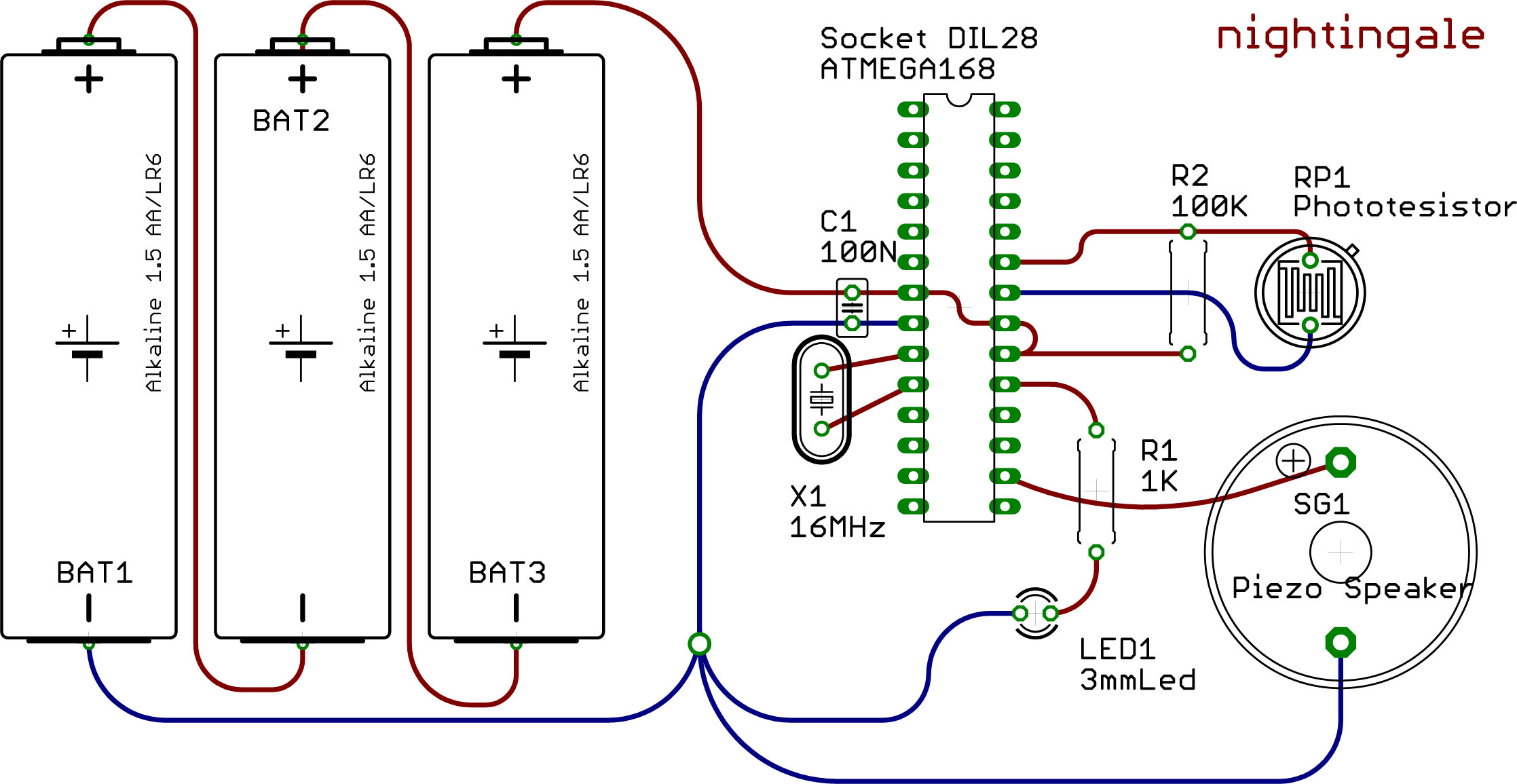
This example demonstrates the utilization of the Watchdog and Sleep functions provided by the ATMEGA 168 microcontroller. These functions are beneficial for developing low-power devices powered by batteries or solar energy. Reduced power consumption is achieved through intermittent operation...

The RF engineer often needs an instrument that can reliably and quickly check a low-frequency quartz crystal unit. However, such equipment is challenging to find, and engineers frequently refer to electronic circuit handbooks for schematics that can perform this...
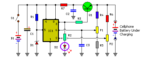
Stops charging when the battery is fully charged. Portable unit for charging mobile phones. Cellphone battery management is a significant issue while traveling, as power supply can be limited. The described circuit functions as an intelligent battery charger designed to...