
1.5 volt LED flasher schematic

The described LED flasher circuit utilizes a 74HC14 hex inverter, a component known for its low power consumption and high efficiency, making it suitable for battery-operated devices. The circuit operates at a nominal voltage of 1.5 volts, powered by a single 'D' cell battery. The design incorporates a square wave oscillator configuration using pins 1 and 2 of the 74HC14, generating a periodic square wave signal that serves as the timing mechanism for the LED flashing.
The alternate flashing of the two LEDs is achieved through additional sections of the hex inverter, which are configured to produce short pulses of approximately 10 milliseconds in duration. This is done by wiring the output of the oscillator to trigger the other inverter sections, allowing the LEDs to flash in a complementary manner. The use of a capacitor charge pump in the output stages is critical, as it boosts the output voltage to provide sufficient current to drive the LEDs effectively. This charge pump mechanism ensures that the LEDs receive the necessary voltage for optimal brightness, even as the battery voltage declines over time.
Current consumption is a crucial aspect of this circuit, with an average draw of 800 microamperes from the 'D' cell. The peak current for the LEDs is approximately 40 milliamperes when the battery is fresh, tapering down to about 10 milliamperes as the battery voltage approaches the cutoff of 1.1 volts. Given the capacity of an alkaline 'D' cell, estimated at 12 amp hours, the theoretical operational lifespan of the circuit is calculated to be around 15,000 hours or roughly 625 days, assuming optimal conditions and no additional load on the battery.
In summary, this LED flasher circuit is designed for longevity and efficiency, effectively utilizing a hex inverter to create a simple yet effective LED flashing mechanism while maintaining low power consumption suitable for extended battery life.This 1.5 volt led fasher runs more than a year on a single 'd" cell and alternately flashes 2 LEDs at about a 1 second rate. The circuit employs a 74HC14 CMOS hex inverter that will operate at very low voltages (less than 1 volt).
One section is used as a squarewave oscillator (pins 1 and 2), while the others are wired to produce a short 10mS pulse on alternate edges of the square wave so the LEDs will alternate back and forth. The output sections each use a capacitor charge pump to increase the voltage for the LEDs. The circuit draws an average current of 800uA from the 'D' battery and the LED peak current is about 40mA with a fresh battery and drops to about 10mA as the battery voltage falls to 1.1 volts. The capacity of a alkaline 'D' cell is about 12 amp hours with a cutoff voltage of 1.1 so the circuit should run about 12/.0008 = 15000 hours or maybe 625 days, but I haven't verified that yet.
🔗 External reference
Related Circuits

This voltage booster circuit for driving one or more white LEDs utilizes a 555 timer as its main component. The timer, designated as IC1, operates as a resettable astable multivibrator with R1, R2, and C2 serving as the timing...
A high voltage power supply DC converter that operates between 3V to 500V has been suggested for use with Geiger tubes. However, during simulation, the output remained at nearly 9V, which matches the input voltage. The schematic drawn has...
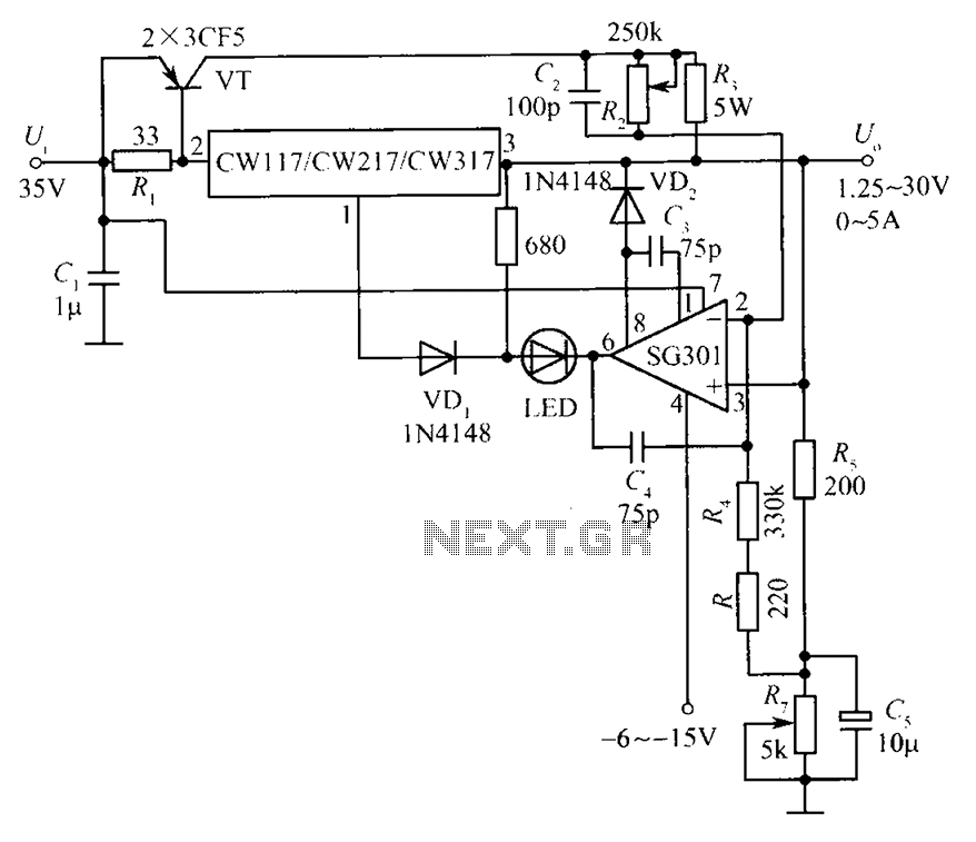
This document presents a diagram of a constant voltage/current power supply box. It is composed of three main components: spread current, constant voltage, and constant current. The design features two 3CF5 power transistors arranged in parallel, functioning as an...
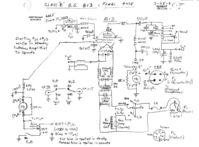
The input impedance of a grounded grid amplifier is typically several hundred ohms. While most vacuum tube transmitters can drive such an impedance without issue, solid-state transmitters, which are designed for loads close to 50 ohms, generally struggle with...
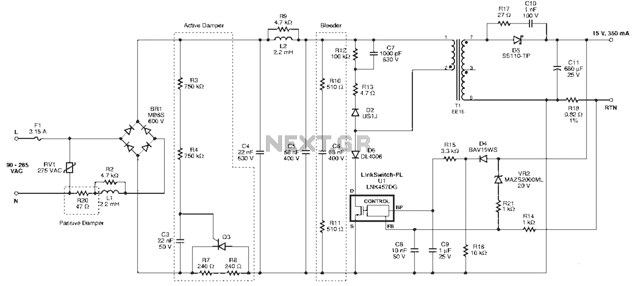
Power Integrations' DER322 reference design employs the LinkSwitch-PL family of LNK460VG devices. This design represents the industry's first alternative 100W A19 incandescent LED driver utilizing a single-layer PCB. It is characterized by low cost, minimal component count, and compact...
The Heater Fan Controller is designed around the PIC12F675 microcontroller. It reads a 10k linear potentiometer and generates appropriately timed pulses to control the DC motor that operates the fan. The lowest setting completely cuts off the power. This...