
LinkSwitch-PL Series LED driver circuit

The DER322 reference design is a significant advancement in LED driver technology, specifically targeting the A19 incandescent bulb replacement market. The LinkSwitch-PL LNK460VG device is central to this design, providing high efficiency and compactness, which are essential for modern lighting applications. The single-layer PCB design not only reduces manufacturing costs but also simplifies assembly, making it an attractive option for manufacturers.
The efficiency rating of over 93% at 230VAC indicates that the design minimizes energy loss, which is crucial for both environmental sustainability and cost-effectiveness in energy consumption. A power factor greater than 0.9 signifies that the driver operates efficiently, reducing wasted energy and improving the overall performance of the lighting system. Additionally, the low total harmonic distortion (THD) of less than 20% ensures that the LED driver does not introduce significant electrical noise into the power supply, which can adversely affect other devices in the circuit.
The inclusion of integrated protection features enhances the reliability of the LED driver. Thermal shutdown with automatic recovery is particularly important in preventing damage to the circuit in the event of overheating, allowing the driver to reset itself once temperatures return to safe levels. This feature contributes to the longevity of the device and ensures consistent performance over time.
Overall, the DER322 reference design exemplifies a modern approach to LED driver solutions, combining efficiency, reliability, and cost-effectiveness in a compact form factor, making it suitable for a wide range of lighting applications. The accompanying circuit diagram provides a detailed representation of the design, showcasing the arrangement of components and their interconnections, which is essential for engineers and designers looking to implement similar solutions in their projects.Powerint's DER322 reference design uses LinkSwitch-PL family LNK460VG devices, the industry's first alternative 100W A19 incandescent LED driver using a single-layer PCB, a low-cost low component count and small size characteristics, efficiency of greater than 93 when 230VAC %, PF greater than 0.9,230 VAC; THD 78 V LED when less than 20%, integrated package protection and reliability features, thermal shutdown automatic recovery. This article describes the alternative A19 incandescent LinkSwitch-PL family of 5W 15V LED driver circuit diagram.
Related Circuits
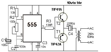
12V power inverter circuit utilizing a 555 timer for an electronic project. The 12V power inverter circuit is designed to convert a DC voltage of 12 volts into an AC voltage suitable for powering small electronic devices. The core component...
This is an inexpensive DC voltage doubler circuit diagram that requires a minimal number of components and is capable of delivering 10V from a 5V power supply. If the oscillator needs to be... The circuit operates on the principle of...
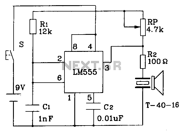
The circuit operates at a distance of 3 feet from the oscillating pulse output of a 555 timer generating a 40kHz signal, driving a T-40-16 transducer to emit ultrasonic signals at the same frequency. The circuit is powered by...
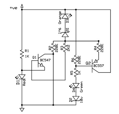
This circuit is a 12V battery checker that utilizes three LEDs to indicate different voltage levels. The red LED illuminates when the battery voltage is between 8V and 10V, the orange LED activates at voltages ranging from 10.5V to...
A video switcher circuit is required to display multiple sources on a single monitor. The circuit schematic below features the MAX454, which serves as the core component of this video switcher. The MAX454 is a video multiplexer-amplifier manufactured by...
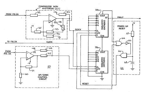
This motor overload circuit allows for short-term overdriving of a system, which is dependent on heat buildup. An overload detection circuit safeguards the motor against currents exceeding the rated current for specific exposure durations. The permissible exposure times are...