
simulation Understanding a high voltage generator circuit

The high voltage DC converter circuit typically employs a transformer-based design to step up the voltage from a lower input level to a higher output level, suitable for applications such as powering Geiger tubes. The circuit generally consists of a switching transistor, a transformer, rectifying diodes, and filtering capacitors.
In this particular case, the use of an equivalent transistor to the 2N4403 may have implications on the switching characteristics of the circuit. The 2N4403 is a general-purpose NPN transistor, and its specifications, such as maximum collector current and switching speed, are critical in determining how effectively it can drive the transformer. If the replacement transistor has different parameters, it may not operate in the desired saturation region, leading to insufficient voltage gain.
The transformer plays a crucial role in stepping up the voltage. The turns ratio of the transformer defines how much the voltage will be increased. If the primary and secondary windings are not properly configured or if there is a mismatch in the winding ratios, the output voltage may not reach the expected levels. Additionally, the orientation of the windings can affect the phase relationship between the input and output, which could lead to reduced efficiency or failure to achieve the desired output.
The selection of diodes is equally important. Diodes are used to rectify the AC voltage generated in the secondary winding of the transformer. If diodes with a lower reverse voltage rating or higher forward voltage drop are used, they may not adequately handle the voltage generated, resulting in a lower output voltage. Furthermore, the recovery time of the diodes can affect the performance of the circuit, particularly at higher frequencies, as slow diodes may not switch off quickly enough, leading to power loss and reduced efficiency.
To troubleshoot the simulation, it would be prudent to verify the specifications of the components used, particularly the transistor and diodes, and ensure they are compatible with the circuit's design requirements. Additionally, examining the transformer turns ratio and ensuring proper winding orientation may help in achieving the expected output voltage. Understanding these factors will provide insight into the circuit's operation and assist in resolving the simulation discrepancies.A high voltage power supply 3V to 500V DC converter and someone suggested a circuit from techlib H. V. generator for Geiger tubes : However, when I tried to simulate it didn`t work, the output is nearly 9V, as the input. In the schematic I drew, the only difference with the proposed circuit is that I used an equivalent of 2N4403 transistor and different diodes.
I also tried reversing one of the winding connections but nothing changed. Could someone explain how this circuit works and how the output is affected by the selection of the diodes Maybe that will also help me understand what`s going wrong with the simulation. 🔗 External reference
Related Circuits
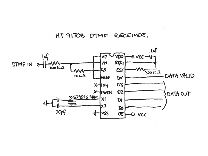
The four data lines from the Keypad Interface connect directly to the data inputs of the Holtek 9200B DTMF Generator (pins 6, 7, 8, and 9). The Inverted Chip Enable output from the Keypad Interface is connected to the...
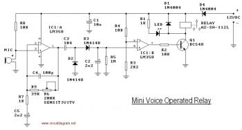
This circuit diagram illustrates a voice-operated relay, which functions similarly to a sound-activated switch circuit. It activates and deactivates the switch based on sound input. The output switch of this circuit is controlled by a relay. The release time...
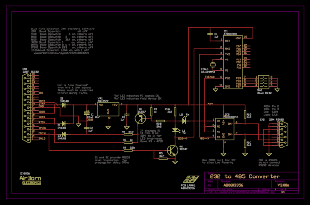
The new version of the RS485 interface addresses the issues associated with RTS control, which was a challenge in the previous design. However, implementing this solution requires a microprocessor, adding complexity to the design. This unit is currently being...
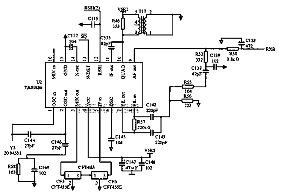
As illustrated in the figure, Vcc is the power supply for the circuit. Upon receiving the initial signal, the frequency is adjusted to 21.7 MHz. This frequency is subsequently enhanced through two crystal filters to improve the selectivity of...
This is a high-power LED driver circuit designed to accommodate a wide input-voltage range. The circuit utilizes a buck/boost converter controller to regulate the current supplied to a white LED. The high-power LED driver circuit is engineered to effectively manage...
Many households are still equipped with tube-type television sets. If there is a desire to connect one of these large televisions to a stereo system to enhance the sound quality... To connect a tube-type television to a stereo system, it...