
1 5 volt led flashers

The LM3909 is a specialized integrated circuit designed for driving LEDs in flashing applications. This IC allows for the creation of visually appealing light patterns with minimal external components. In the described circuit, the primary components include the LM3909 IC, a timing capacitor, and an LED, which collectively enable the flashing effect.
The 1.5-volt battery serves as the power source, providing sufficient voltage for the LM3909 to operate effectively. The timing capacitor, when connected to the LM3909, determines the flashing frequency of the LED. By selecting a capacitor of appropriate capacitance, the time interval between flashes can be adjusted, allowing for customization of the visual effect.
The LED is connected to the output pin of the LM3909, which drives the LED on and off according to the timing set by the capacitor. The circuit can be further enhanced by adding resistors to limit the current through the LED, ensuring its longevity and preventing damage.
This simple yet effective LED flasher circuit can be utilized in various applications, such as decorative lighting, indicators, and signaling devices. Its low power consumption makes it suitable for battery-operated devices, while the ease of assembly and minimal component requirements contribute to its popularity among hobbyists and engineers alike.The LED flasher circuits below operate on a single 1.5 volt battery. The circuit on the upper right uses the popular LM3909 LED flasher IC and requires only a timing capacitor and LED.. 🔗 External reference
Related Circuits
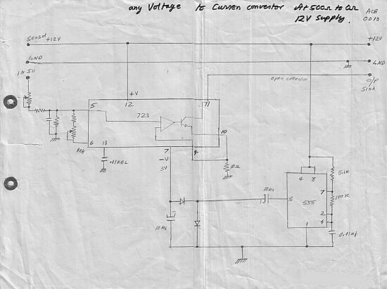
This circuit converts a voltage control output from a process controller into a current control signal, suitable for applications such as AC drives or valves requiring a current control signal. It operates as a three-wire voltage-to-current loop converter. The...
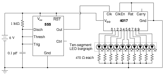
The following circuit illustrates a schematic diagram of an LED sequencer. This circuit is based on the 555 timer integrated circuit (IC). Features include a 555 timer circuit designed to debounce a mechanical switch, a 555 timer circuit to...
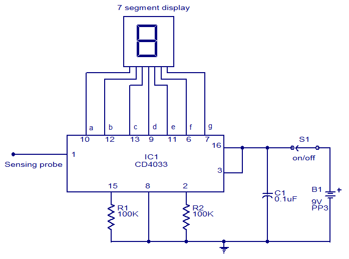
This circuit is designed to test the presence of mains voltage without direct electrical contact with the mains line. The core component of this circuit is the CMOS IC CD4033, which features a five-stage decade Johnson counter and an...
To obtain the power supply graphs on the previous page, the circuit is designed to independently monitor the power sources with the addition of a few resistors. Diode D3 allows the solar panel voltage to charge the batteries, while...
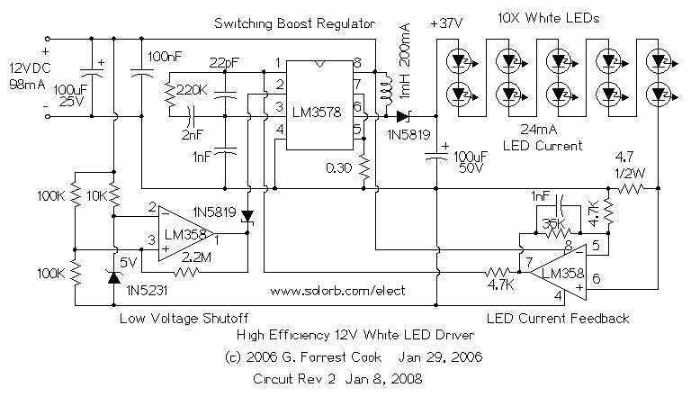
The heart of the circuit is a string of 10 white LEDs. These are wired in series and connected to a current-regulated step-up switching power supply circuit. DC powered LED lighting circuits can vary from the trivial, with a...
The circuit diagram of an IC Controlled Emergency Light with Charger, also known as a 12V to 220V AC inverter circuit, is presented here. This circuit features automatic activation of the light during mains failure and includes a battery...