
Wireless mains voltage tester

The circuit employs the CD4033 CMOS IC, which is known for its low power consumption and high noise immunity, making it ideal for applications involving sensitive detection of voltage. The five-stage Johnson counter within the IC allows for counting up to ten, which is displayed on a standard seven-segment LED display. The sensor wire acts as an antenna, picking up electromagnetic signals from the nearby mains line. The length and insulation of the wire are critical; however, the description mentions it as 0 cm, which is likely a typographical error and should refer to a practical length that allows effective sensing without direct contact.
When the sensor wire is placed near an energized mains wire, the alternating electromagnetic field induces a small AC voltage in the wire. This induced voltage triggers the clock input of the CD4033, causing it to increment its count. The output from the IC is then sent to the seven-segment display, which visually indicates the count from zero to nine, repeating this sequence as long as mains voltage is present.
For optimal performance, it is recommended to shield the sensor wire to minimize interference from other electromagnetic sources and ensure that the circuit is housed in a non-conductive enclosure to prevent accidental contact with live components. Proper power supply decoupling for the CD4033 is also essential to maintain stable operation, particularly in environments with fluctuating mains voltage. This circuit is useful for electricians and technicians who need to safely check for live wires without the risk of electric shock.This circuit can be used to test whether mains voltage is present or not without having electric contact with mains line. The CMOS IC CD4033 is the heart of this circuit. The CD4033 consists of a 5 stage decade Johnson counter and an output decoder for converting the Johnson code to a 7 segment decoded output for driving 7 segment LED display.
A 1 0cm long insulated copper wire connected to the clock pin (pin1) of the IC serves as the sensor. The sensor wire has to be placed in the vicinity of the mains wire to be tested. When there is no voltage in the mains line, no voltage will be induced in the sensor wire and the display will show a random digit. When there is voltage in the mains line, a small voltage will be induced in the sensor wire due to electromagnetic induction and this voltage is sufficient enough to clock the CMOS IC CD4033.
Now the display will count from zero to nine and repeat. 🔗 External reference
Related Circuits
Home appliances are typically controlled using switches, sensors, and similar devices. However, physical interaction with switches can pose risks, particularly in the event of short circuits. The circuit presented here eliminates the need for physical contact to operate the...
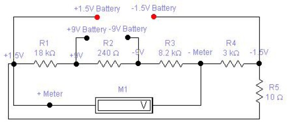
The circuit diagram of a DC battery tester designed by Matthew B. This circuit can measure DC batteries ranging from 1.5V to 9V. Component Parts List: R1 = 18K Ohm, R2 = 240 Ohm, R3 = 8.2K Ohm, R4...

The infrared (IR) detector diode D1 captures the IR signal at approximately 40 kHz and transmits it to U1, a high-gain preamplifier, which then sends the signal to U2, a 4046 phase-locked loop (PLL) configured as a frequency modulation...
The circuit in the diagram generates a negative voltage without using integrated circuits. It utilizes five n-p-n transistors driven by an approximately 1 kHz TTL clock. When the clock input is high, transistors T1 and T2 connect capacitor C1...

The AD654 voltage-frequency converter is a low-cost device that operates with a single supply voltage ranging from +5V to +36V, as well as with dual supplies of +5V to +18V. It can handle a maximum input voltage of 36V...

The 12kV High Voltage Generator utilizes a unique adjustment to generate approximately 12,000 volts with a current of about 5 µA. It consists of two SCRs forming two triggering circuit paths. These SCRs discharge a 0.047 µF, 400V capacitor...