
Schematic Diagram Of LED Sequencer Based On The 555 Timer IC

The LED sequencer circuit employs the 555 timer IC in astable mode to create a continuous pulse output. The frequency of these pulses can be adjusted by changing the resistor and capacitor values connected to the timer. The output of the 555 timer is fed into a 4017 decade counter, which counts the pulses and activates the connected LEDs in a sequential manner. Each output pin of the 4017 corresponds to a specific LED, illuminating them one after another as the timer generates pulses.
To debounce the mechanical switch, a separate 555 timer configuration is utilized. This ensures that when the switch is pressed, any bouncing effect does not cause multiple unintended pulses to be sent to the counter. The pulldown resistor is critical in this setup, ensuring that the input to the timer remains stable when the switch is not pressed, preventing false triggering.
The circuit's power supply is typically provided by a battery, ensuring portability and ease of use. The inclusion of diodes may also be present to protect against reverse polarity, ensuring that the circuit operates safely under various conditions. Capacitors are used to smooth out voltage fluctuations, providing a stable operating environment for the 555 timer and 4017 counter.
Overall, this LED sequencer circuit is an excellent example of using basic electronic components to create a visually engaging output while demonstrating fundamental principles of timing and counting in electronics.The following circuit shows about Schematic Diagram Of LED Sequencer. This circuit based on the 555Timer IC. Features: 555 timer circuit to debounce a mechanical switch, 555 timer circuit to produce clock pulses, pulldown resistor, 4017 decade counter/divider circuit for frequency division, frequency divider and timepiece (wa tch) to measure frequency, 4017 decade counter/divider circuit to produce a sequence of pulses. Component: IC, Resistor, Diode, Battery, Capacitor. [ learningelectronics. net ] 🔗 External reference
Related Circuits
LED displays consist of arrays of Light Emitting Diodes (LEDs) arranged in various shapes to convey specific information. The operation of LED displays is similar to that of standard LEDs, requiring straightforward connections when sufficient microcontroller pins are available....
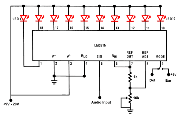
This is a simple audio sound level LED display circuit diagram. The circuit is entirely based on a single integrated circuit, the LM3915 from National Semiconductor. The LM3915 is a monolithic integrated circuit that displays the audio sound level...
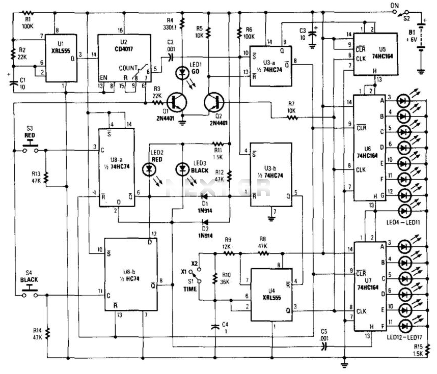
This circuit utilizes a timer to produce pulses at a 5-ms clock rate. The pulses are sequentially shifted into a shift register, illuminating an LED. An auxiliary timer generates one pulse per second to activate the "go" LED and...
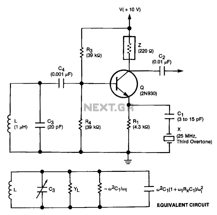
This unit is easily tunable and stable, consumes minimal power, and is more cost-effective than other types of oscillators that operate at similar frequencies. This unique combination of features is made possible by a design concept that involves operating...
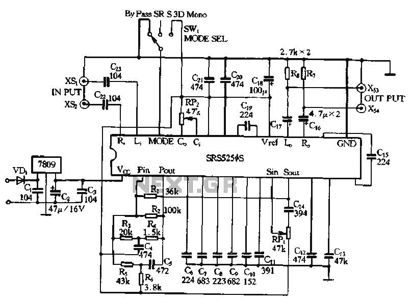
Typical application circuits for the Zheng brick SRS5250S are illustrated in the provided diagram. The SRS5250S features a pin diagram and a processing circuit that allows the user to switch between three operating modes: straight, SRS, and single-channel analog...
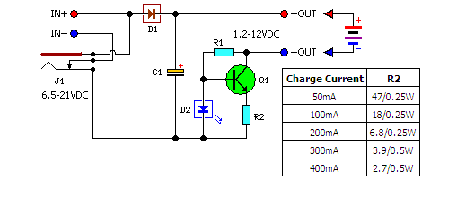
A low-cost solution for charging both NiCd and NiMH batteries is presented. The circuit diagram illustrates a universal charger designed for these battery types. The circuit for the low-cost universal charger for NiCd and NiMH batteries typically incorporates several key...