
1,500W / 4 Ohms Power Amplifier

This amplifier is designed to deliver a peak power output of 2kW and a minimum continuous power output of 1.5kW. This high power output capability implies that it can potentially damage any speaker connected to it. This is due to the fact that, despite the power handling claims made by various driver manufacturers, these drivers are unable to handle such high power levels.
To further illustrate this point, consider connecting the most robust and powerful driver available, rated at 8 ohms, directly to the 110V mains. Although this is suggested as a theoretical exercise and not recommended in practice, it serves to highlight the power handling limitations of typical drivers. In this scenario, the driver would be subjected to an RMS voltage of 110V, which equates to a power level of 1,500W. This is a significant amount of power and is likely to cause damage to the driver.
In conclusion, the amplifier in question is capable of delivering high power levels that exceed the power handling capabilities of most drivers. This is an important consideration when selecting speakers to be used with this amplifier, as it is essential to ensure that the speakers are capable of handling the power output of the amplifier to avoid potential damage.Capable of 2kW peak and a minimum of 1.5kW continuous, it has to be said that this amplifier will blow up any speaker connected to it. Regardless of the claimed power that various drivers can handle, they can`t. To put this whole issue into perspective, take the most powerful and robust driver you can (8 ohms), and connect it directly to the 110V mains (I recommend this as a `thought experiment`, rather than actually doing it!).
110V RMS into 8 ohms is 1,500W. 🔗 External reference
Related Circuits
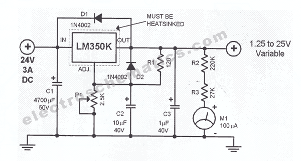
This regulated power supply is adjustable between a few volts and 15V using P1, while P2 is used to set the upper limit at 15.0V. The value of R6 is calculated as 0.7V divided by Imax, where Imax represents...
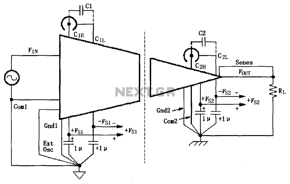
The basic connection circuit for ISO120/121 includes signals and power supply. Each power supply terminal must have a 1 µF tantalum capacitor as a bypass filter, and the printed circuit board layout should allow for the bypass capacitor to...
The ADF4107 Frequency Synthesizer can be used to implement local oscillators in the upconversion and downconversion sections of wireless receivers and transmitters. It consists of a low noise digital phase frequency detector (PFD), a precision charge pump, a programmable...
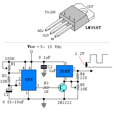
Power pulse circuit using LM350 and NE555. This circuit can be used to drive lamps, power LEDs, DC motors, etc. Adjust R5 for output amplitude and R1 for output power. The LM350 is an adjustable 3-terminal voltage regulator. The power...
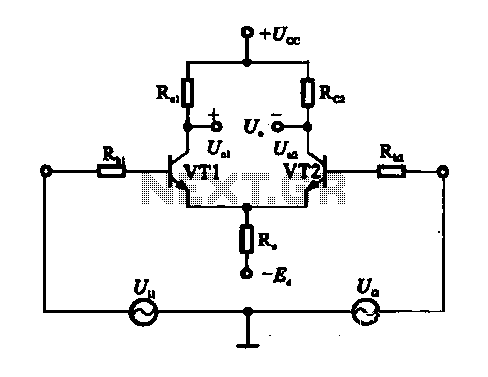
An emitter-coupled differential amplifier circuit is designed to suppress zero drift through circuit symmetry. The effectiveness of zero drift suppression improves with better symmetry; however, in practice, achieving complete symmetry is not feasible. Consequently, the basic differential amplifier circuit...
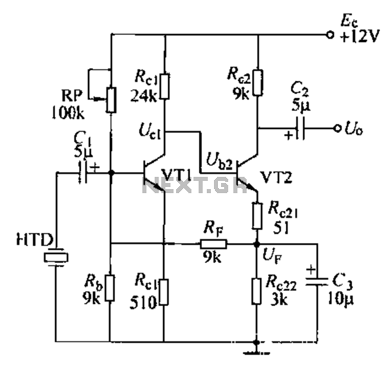
Dctl is a two-stage amplifier, with the first stage amplifying the collector voltage of transistor VT1. The second stage, represented by VT2, is proportional to the current flowing through the winding. The RF signal is applied to the sub-base...