
Emitter-coupled differential amplifier

The emitter-coupled differential amplifier is a critical component in analog signal processing, providing high gain and excellent common-mode rejection. The circuit typically consists of two transistors configured in a differential arrangement, where the emitters are connected together and biased with a common resistor. This configuration allows for the amplification of the difference between the input signals while minimizing the amplification of any common signals, effectively reducing noise and interference.
The zero drift phenomenon can significantly impact the performance of precision amplifiers. In an ideal scenario, the circuit would maintain perfect symmetry, thus ensuring that any offset voltages introduced by the transistors would cancel each other out. However, real-world components exhibit variations in characteristics, leading to unavoidable imbalances. The design modification mentioned involves the strategic placement of the emitter resistor to enhance the overall symmetry of the circuit, which in turn helps to mitigate zero drift effects.
By employing a dual DC power supply, the circuit can eliminate the need for additional biasing resistors. This simplification not only reduces component count but also minimizes potential sources of error and instability within the circuit. The specific configuration allows for a more straightforward design while maintaining the desired performance metrics.
In summary, the emitter-coupled differential amplifier serves as an essential tool in high-precision applications, where signal integrity is paramount. The design considerations taken to address zero drift and enhance symmetry directly contribute to the reliability and accuracy of the amplifier's output, making it suitable for various electronic applications.Emitter-coupled differential amplifier (1) emitter-coupled differential amplifier circuit in the base of the differential amplifier circuit is by symmetry of the circuit to sup press the zero drift, the better the symmetry, the inhibitory effect of zero drift good. But in fact the circuit can not be completely symmetrical, so that the basic differential amplifier circuit for zero drift suppression to be subject to greater restrictions. Change into the way is the basic amplifier circuit emitter resistor connected to a roll, as shown in FIG.
Has been able to save two bias resistor Rb12 and Rb22, because a dual DC power supply. Below is a brief description of how it works.
Related Circuits
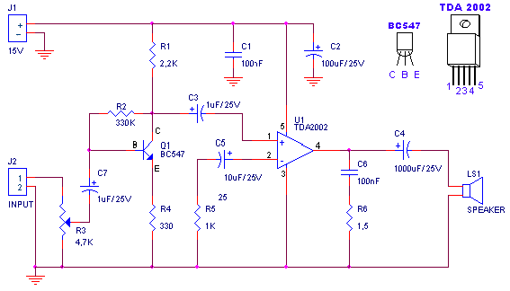
A small amplifier with nice characteristics: Tendency of catering: 15V. Force of expense: 4.2Wrms in the 4W. Minimal signal of entry: 94mVp-p with preamplifier, 0.65Vp-p without the preamplifier. More: Materially: R1=2.2kΩ R2=330kΩ R3=4.7kΩ logarithmic potentiometer R4=330Ω R5=1kΩ R6=1.5Ω C1,...
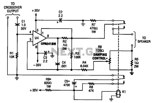
Designed to power a low-frequency subwoofer speaker system, the amplifier can deliver up to 100 W into an 8-ohm load. The OPA541BM operational amplifier, produced by Burr-Brown Corporation, necessitates heatsinking for optimal performance. Additionally, the design incorporates a damping...
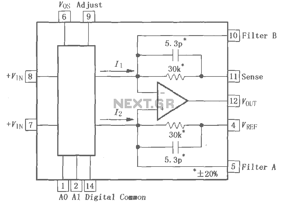
The PGA202 is a digitally controlled programmable gain amplifier with gain settings of G = 1, 10, 100, and 1000. The PGA203 offers gain settings of G = 1, 2, 4, and 8. Both amplifiers are compatible with CMOS...
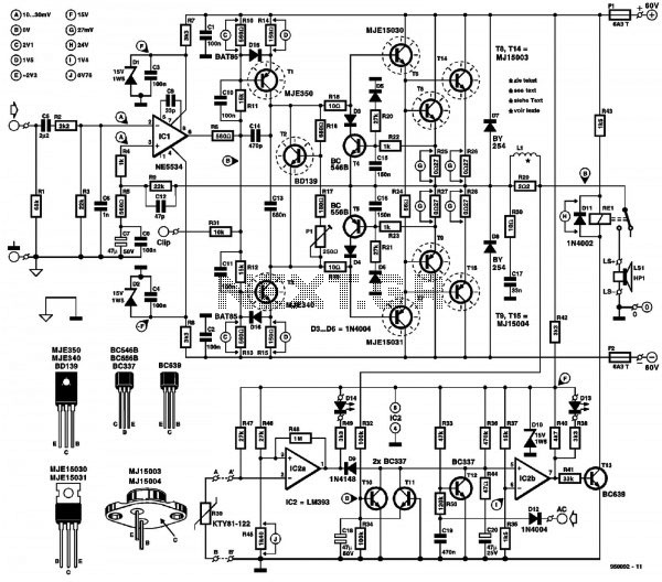
A conventional power amplifier featuring both high-pass and low-pass filters. Powered by a 60V DC supply, this circuit can deliver approximately 300W of sound power. The operational amplifier NE5534 is utilized in the configuration. The described power amplifier circuit integrates...
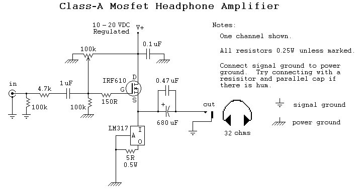
Dissatisfied with the performance of a computer soundcard when driving 32-ohm headphones, a decision was made to construct a Class-A MOSFET headphone amplifier. The objective was to maintain simplicity, minimize costs, and utilize salvaged components whenever possible. This project...
The circuit is based on a single operational amplifier integrated circuit designed to produce a modular preamplifier that operates in Class A configuration. The modular preamplifier circuit utilizes a single operational amplifier (op-amp) integrated circuit, which serves as the primary...