
1,5V Earphones Audio Amplifier

This audio amplifier circuit is designed to enhance sound detection, particularly for users in environments such as theaters, cinemas, and lectures. The circuit operates with a 1.5V battery, making it portable and convenient for personal use. The input from a miniature electret microphone (MIC1) is crucial for capturing audio signals, which are then processed by a series of components to achieve the desired amplification.
The circuit utilizes a constant-volume control amplifier configuration, primarily facilitated by the transistors Q1, Q2, and Q3. Q1 is responsible for amplifying the audio signals, while Q3 serves to adjust the bias of Q1, ensuring that the output remains at a constant level of approximately 1 Volt peak to peak. This design allows the circuit to effectively amplify low amplitude sounds while simultaneously limiting higher amplitude signals to prevent distortion.
The inclusion of various resistors (R1 to R9) serves multiple purposes, such as setting bias points, controlling gain, and ensuring stability in the circuit. For instance, R2 plays a critical role in modifying the bias of Q1, thereby influencing its AC gain. The potentiometer (P1) allows for user-controlled volume adjustment, providing flexibility in sound levels.
Capacitors C1, C2, C3, C6, C4, and C5 are employed for coupling, decoupling, and filtering purposes, ensuring that the audio signals remain clean and free from unwanted noise. The diode (D1) is included for protection against reverse polarity, safeguarding the circuit components from potential damage.
The output is designed to connect to 32 Ohm impedance mini-earphones via a stereo 3mm jack socket (J1), allowing users to listen to amplified sounds discreetly. The circuit's typical current draw of 7.5mA is efficient for battery-powered applications, ensuring a reasonable operational lifespan without frequent battery changes.
Overall, this audio amplifier circuit is an effective solution for enhancing sound detection in various environments, providing users with the ability to hear subtle sounds that may otherwise go unnoticed.This audio amplifier circuit, connected to 32 Ohm impedance mini-earphones, can detect very remote sounds. Useful for theatre, cinema and lecture goers: every word will be clearly heard. You can also listen to your television set at a very low volume, avoiding to bother relatives and neighbors.
Even if you have a faultless hearing, you may discover unexpected sounds using this device: a remote bird twittering will seem very close to you. The heart of the circuit is a constant-volume control amplifier. All the signals picked-up by the microphone are amplified at a constant level of about 1 Volt peak to peak. In this manner very low amplitude audio signals are highly amplified and high amplitude ones are limited.
This operation is accomplished by Q3, modifying the bias of Q1 (hence its AC gain) by means of R2. A noteworthy feature of this circuit is 1,5V battery operation. Typical current drawing: 7,5mA. List Component P1: 22K Log. Potentiometer R1,R9: 10K 1/4W Resistors R2: 1M 1/4W Resistor R3: 4K7 1/4W Resistor R4,R7: 100K 1/4W Resistor R5: 3K9 1/4W Resistor R6: 1K5 1/4W Resistor R8: 100R 1/4W Resistor C1,C2: 100nF 63V Polyester or Ceramic Capacitors C3,C6: 1µF 63V Polyester or Ceramic Capacitors C4: 10µF 25V Electrolytic Capacitor C5: 470µF 25V Electrolytic Capacitor D1: 1N4148 75V 150mA Diode Q1,Q2,Q3: BC547 45V 100mA NPN Transistors Q4: BC337 45V 800mA NPN Transistor MIC1: Miniature electret microphone SW1: SPST Switch J1: Stereo 3mm. Jack socket B1: 1.5V Battery 🔗 External reference
Related Circuits
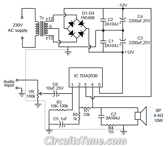
All ground points in the circuit should be connected to a single point and grounded if possible, or connected to the transformer's 0V marked wire as shown in the circuit. In electronic circuit design, proper grounding is crucial for maintaining...
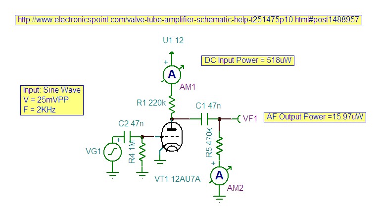
This mini audio amplifier will test the audio stages in amplifiers such as the front end of FM bugs. You can also use it on lots of our other projects as well as the output stages of radios. It...
Incorporate resistors in a parallel configuration to enhance audio input. To control the volume for each input channel, integrate a linear trimmer or potentiometer with the following configuration: pin 1 connects to ground, pin 2 serves as the output,...
It is unlikely that the device was designed to be powered by a 9V battery, as they are not very robust. The battery life is typically under 2 hours when using an alkaline battery. The power requirements of electronic devices...
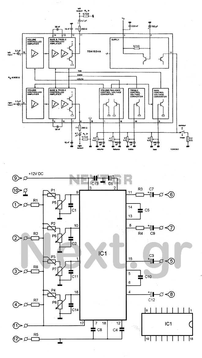
The circuit utilizes the TDA1524 chip, which is an integrated control unit for volume, bass, treble, and balance adjustments. Control is achieved through four potentiometers (P5-P8). The integrated circuit IC1 requires very few external components to operate. Potentiometers P1-P4...
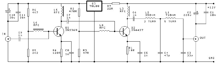
This project involves a 250mW RF power amplifier circuit. It is designed to amplify the output of approximately 7mW wideband FM transmitters to a final output level of about 250mW. The circuit utilizes a simple two-transistor VHF power amplifier...