
Simple Audio Mixer circuit

To achieve improved audio input through the use of resistors in parallel, it is essential to understand the implications of this configuration. When resistors are connected in parallel, the total resistance decreases, which allows for a greater current to flow through the circuit. This characteristic is beneficial for audio applications, as it can increase the overall signal strength and improve the mixing of multiple audio sources.
For volume control, the linear trimmer or potentiometer serves as an adjustable resistor, allowing for fine-tuning of the audio levels. The specified pin configuration is critical for proper functionality. Pin 1, connected to ground, establishes a reference point for the circuit. Pin 2, designated as the output, delivers the adjusted audio signal to subsequent stages in the system. Pin 3, acting as the input, receives the audio signal that is to be modified.
When designing the circuit, it is advisable to select resistors with appropriate values to ensure that the desired audio characteristics are achieved without introducing excessive noise or distortion. The choice of the potentiometer value should also be considered, as it will affect the range of volume control available. Typically, a potentiometer value of 10kΩ to 100kΩ is suitable for audio applications, but the specific requirements may vary based on the overall circuit design.
In summary, the integration of parallel resistors and a linear trimmer or potentiometer into an audio input circuit can significantly enhance functionality. Proper attention to component selection and configuration will ensure optimal performance and user experience in audio applications.Add some resistors in parallel connection for more audio input. To adjust the volume for each input channel, add linear trimmer or potentiometer with configuration: pin1> ground; pin2>output; pin 3>input 🔗 External reference
Related Circuits
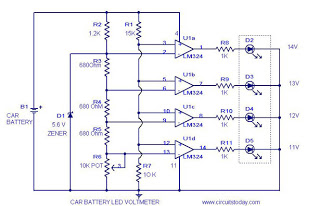
This circuit is a practical device that, when installed in a vehicle, displays the voltage of the car battery using an LED dot display. The meter circuit utilizes four comparators formed from a quad op-amp, specifically the LM324. The...
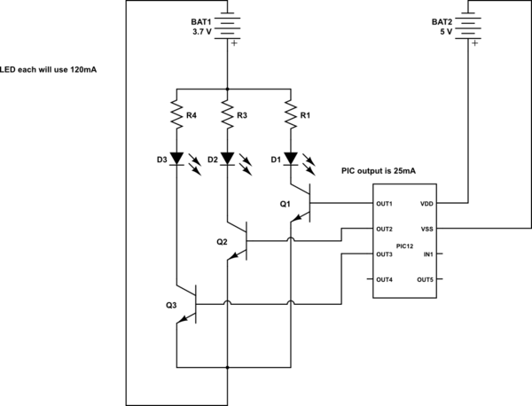
This is a conceptual schema utilizing a PIC12 microcontroller to control the blinking of three LEDs, each exhibiting different blinking patterns. There are several questions that need to be addressed. The circuit design involves a PIC12 microcontroller, which is a...
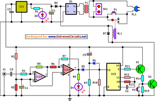
This circuit deactivates an amplifier or any connected device when a low-level audio signal is absent at its input for at least 15 minutes. Activating switch P1 powers the device, enabling operation of any appliance connected to SK1. The...
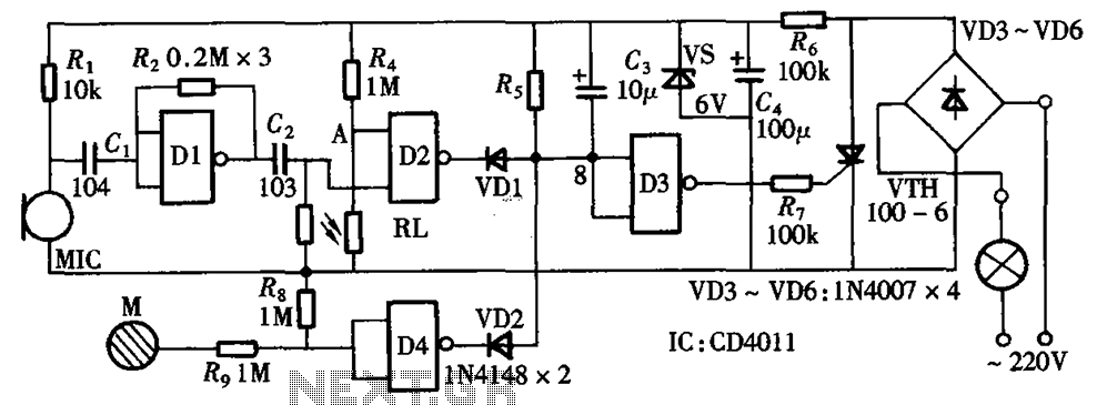
The circuit integrates sound and light control with touch functionality, creating a fully operational delay section light switch circuit. It consists of light control, voice circuits, and a touch control circuit, all triggered by a thyristor switch. The described circuit...
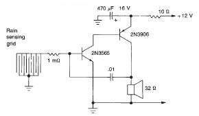
This rain detector electronic circuit project is a simple alarm circuit that activates an audio warning when liquid is detected on the sense pad. The circuit diagram is based on two transistors. When the sense pad conducts, transistors Tr1...
This DC drill speed controller circuit allows for the adjustment of the rotational speed of a drilling machine. A mini-drill machine is always... This circuit utilizes a pulse-width modulation (PWM) technique to control the speed of a DC motor, which...