
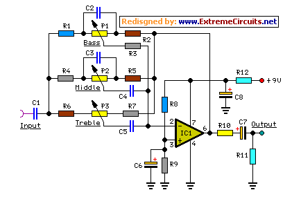
10W audio amplifier circuit by TDA2030

In electronic circuit design, proper grounding is crucial for maintaining signal integrity and minimizing noise. The recommendation to connect all ground points to a single point is known as a star grounding technique. This approach helps to prevent ground loops, which can introduce unwanted interference and degrade the performance of the circuit.
When implementing this design, it is essential to ensure that the ground connections are made using low-resistance paths to avoid voltage drops that could affect circuit operation. The ground point can be physically located at the power supply's negative terminal or at a designated ground plane on a printed circuit board (PCB).
If a transformer is used, the recommendation to connect to the 0V marked wire indicates that this wire serves as a common reference point for the circuit's ground. Care should be taken to ensure that the transformer is properly rated and that its grounding scheme aligns with the overall circuit design to maintain safety and functionality.
In summary, the grounding strategy described emphasizes the importance of a unified ground reference in circuit design, which is essential for reliable operation and performance optimization.All ground point in the circuit should be connected in a single point and ground it(If possible) or connect in transformer`s 0 marked wire as shown in the circuit. 🔗 External reference
Related Circuits

This document illustrates the configuration of the high-precision, high-impedance OPA2111 amplifier. The total voltage circuit is designed for a magnification of Av = 10 (1 + 2R2 / R1), achieving a total gain of 1000 times. A gain stage...
High-quality modular design, powered by a 9V battery, with very low current consumption. The objective of this project was to design a small, portable mixer. The project focuses on creating a compact audio mixer that operates efficiently on a 9V...
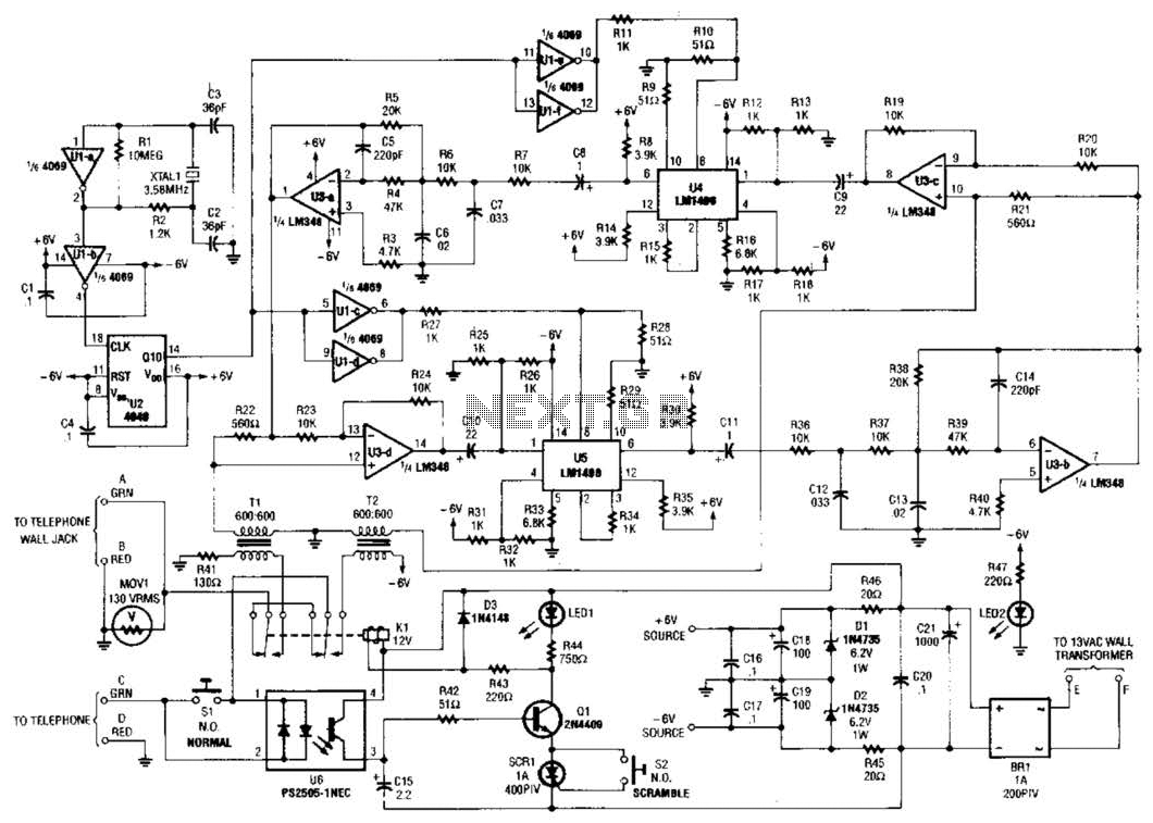
Two hybrids (T1 and T2) are utilized to facilitate a direct connection to a telephone line. This circuit employs a standard speech-inversion algorithm, which inverts the frequency of an audio signal around a central frequency. An LM1496 balanced modulator...

A temperature-controlled pulse-width-modulator (PWM) boost converter circuit diagram is illustrated in the following figure. This boost converter is designed to operate a 12V fan using a 5V supply while maintaining temperature control. The temperature-controlled PWM boost converter circuit operates by...
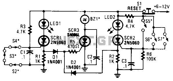
In this circuit, a low-powered silicon-controlled rectifier (SCR) is utilized to trigger a higher-powered SCR. When a switch is opened (S2, S3, S4) or closed (S5, S6, S7), either SCR1 or SCR2 is activated. This action subsequently triggers SCR3...
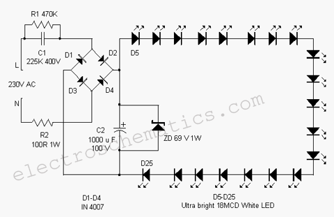
This white LED light illuminates the porch with cool white light. The circuit features a simple and energy-saving design. Its current consumption is practical. The white LED light circuit is designed to provide efficient illumination while minimizing energy usage. The...