
1.5V Joule Thief 2.0 circuit

The two-transistor Joule Thief is a compact and efficient circuit designed to extract energy from low-voltage sources, such as depleted batteries. This circuit typically consists of two NPN transistors, a few passive components, and a transformer. The main purpose of the Joule Thief is to boost the voltage from a low-power source to a usable level, making it particularly useful for powering small electronic devices.
In the schematic, each transistor plays a crucial role in the oscillation process. The first transistor is responsible for initiating the oscillation by turning on and allowing current to flow through the primary winding of the transformer. This current generates a magnetic field, which induces a voltage in the secondary winding. As the magnetic field collapses, the induced voltage can be significantly higher than the original input voltage. The second transistor acts as a feedback mechanism that helps sustain the oscillation by providing additional current to the first transistor when the voltage at the base of the first transistor exceeds a certain threshold.
The passive components, including resistors and capacitors, are strategically placed to control the timing and frequency of the oscillation, as well as to ensure stable operation of the transistors. The circuit typically includes a feedback resistor that connects the collector of the first transistor to its base, which is essential for maintaining the oscillation. Additionally, a small capacitor may be used to filter out noise and stabilize the voltage levels in the circuit.
Overall, the two-transistor Joule Thief is a simple yet effective design that showcases the principles of inductive energy transfer and transistor operation, making it a popular project among electronics enthusiasts and hobbyists.I saw this Youtube video of a schematic of a two transistor Joule Thief by Sanjev21. I notice that this video has been removed. 🔗 External reference
Related Circuits
Do you long for a beach holiday on a tropical island, but you don't have the necessary means? There is a solution: build the i-TRIXX surf simulator, put on your headphones, and escape from this mundane reality. Allow the...
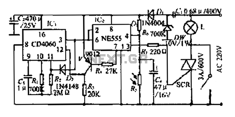
A photosensitive daytime electricity circuit utilizes a very small positive voltage. It features a 555 timer IC with four pins, including a reset pin that operates at low voltage. The circuit includes a bidirectional thyristor (iSCR) that controls lighting,...
This circuit will allow you to connect any tape recorder that has a mic and remote input to a phone line and automatically record both sides of a conversation whenever the phone is in use. You will need to...
The TDA8444 is a digital-to-analog (D/A) converter integrated circuit (IC) produced by Philips. It is designed to convert digital signals into analog signals. The TDA8444 IC utilizes a 16-pin dual in-line package, with specific pin functions and data outlined...

This circuit should be connected prior to the amplifier circuit. To achieve optimal performance, it is recommended to utilize high-quality electronic components such as metal film resistors, MKM capacitors (non-polar), and tantalum capacitors (bipolar). The power supply module can...
The circuit operates on the principle of detecting smoke produced during a fire, which passes between a light bulb and a light-dependent resistor (LDR). As smoke obscures the light, the amount of light reaching the LDR decreases, resulting in...