
Smoke Detector Circuit

The optical smoke detector circuit utilizes a light bulb and an LDR to detect smoke through changes in light intensity. When smoke enters the detection area, it scatters the light emitted from the bulb, thereby reducing the light intensity that reaches the LDR. The increased resistance of the LDR leads to a higher voltage at the transistor's base, allowing current to flow to the COB, which activates the alarm system.
Key components of the circuit include the light bulb, LDR, a transistor, the RE46C190 IC, and the TGS 813 gas sensor. The RE46C190 serves as the central processing unit, managing the smoke detection process. The internal oscillator within the IC is crucial for maintaining low power consumption by periodically activating the smoke detection circuitry.
The placement of the bulb and LDR is critical for achieving the desired sensitivity. The preset variable resistor (VR1) allows for fine-tuning of the circuit's response to smoke, enabling adjustments based on the specific environment in which the detector is installed. The TGS 813 gas sensor is particularly effective in detecting smoke and other combustion gases, making it a suitable choice for this application.
In summary, this smoke detector circuit is designed for educational and project purposes rather than as a primary safety device in residential settings. Its simplicity and low power requirements make it an excellent choice for electronic projects focused on fire detection, providing essential functionality with minimal components. Proper installation and calibration are essential to ensure effective operation in detecting potential fire hazards.It relies on the smoke that is produced in the event of a fire and passes between a bulb and an LDR, the amount of light falling on the LDR decreases. This type of circuit is called optical smoke detector. Do not use it as a home smoke detector it`s jus for electronic projects. This causes the resistance of LDR to increase and the voltage at the base of the transistor is pulled high due to which
the supply to the COB (chip-on-board) is completed. The sensitivity of the smoke detector depends on the distance between bulb and LDR as well as setting of preset VR1. Thus by placing the bulb and the LDR at appropriate distances, one may vary preset VR1 to get optimum sensitivity.
Using this photoelectric smoke detector circuit can be designed a very simple and low power smoke detector alarm project that is based on the RE46C190 smoke detector IC. With minimal external components, this smoke detectors alarm circuit will provide all the required features for a photoelectric smoke detector type electronic project.
The design incorporates a gain-selectable photo amplifier for use with an infrared emitter detector pair. An internal oscillator strobes power to the smoke detection circuitry every 10 seconds, to keep the standby current to a minimum.
If smoke is sensed, the detection rate is increased to verify an Alarm condition. The simple schematic diagram of a smoke detector presented here utilizes the gas sensor TGS 813 as the main detecting component. The circuit is pretty easy to build and performs useful fire hazard detection once installed into a possible fire prone zone.
🔗 External reference
Related Circuits
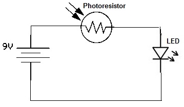
A simple photoresistor circuit will be constructed to demonstrate the operation of a photoresistor, which activates the circuit in the presence of light and deactivates it in darkness. This circuit connects a photoresistor to an LED. When the photoresistor...

This second-order low-pass filter utilizes a 741 operational amplifier and can be tuned from 2.5 kHz to 25 kHz. The circuit is beneficial in audio and tone control applications. R1 and R2 are ganged potentiometers. The described circuit features a...

This circuit is similar to the LED clock using 12 neon indicator lamps instead of LEDs. It operates from 2 high capacity ni-cad cells (2.5 volts) which keep it going for a couple weeks. High voltage (70 volts) for...

This system utilizes an MM5369 integrated circuit (IC) to generate a 60 Hz signal from a television burst crystal operating at 3.579 MHz. The components F8 and V9 produce 10 Hz and 1 Hz signals derived from the 60...

This PIC-based hardware circuit accepts texts from a PS/2 keyboard and converts it into a Morse code audio signal. The described circuit utilizes a PIC microcontroller to interface with a PS/2 keyboard, allowing for the input of alphanumeric characters. The...

The adjustment potentiometer for the Raspberry Pi can modify the conduction angle of the thyristor VI and V2, which in turn adjusts the speed of the DC motor M. The speed feedback circuit is implemented using a tachometer generator...