
Telephone Record Control Circuit

This circuit is designed to facilitate the automatic recording of telephone conversations by utilizing a tape recorder equipped with a microphone and remote input. The primary components of the circuit include a field-effect transistor (FET) and two additional transistors, designated as Q2 and Q3. The operation of the circuit hinges on the voltage levels present on the phone line, which vary depending on whether the phone is in use or not.
In the idle state (on hook), the phone line maintains a voltage of approximately 48 volts DC. Under these conditions, the FET remains in the off state, which in turn keeps transistors Q2 and Q3 also in the off state, preventing any current from reaching the tape recorder. This ensures that the recorder remains inactive and does not record any background noise or unintended audio.
When the phone is taken off hook, the line voltage drops to below 10 volts DC. This change in voltage activates the FET, switching it into the on state. As a result, transistors Q2 and Q3 are also turned on, allowing current to flow to the tape recorder. It is critical that the tape recorder is pre-set to the record mode, as this ensures that any audio from the conversation will be captured immediately upon activation.
Before installation, it is essential to assess the polarity of both the phone line and the tape recorder's remote input. Proper connections must be made according to the determined polarities to ensure correct functionality and to avoid damage to the components. The circuit effectively harnesses the phone line as a power source, eliminating the need for an external power supply, which simplifies the setup and enhances portability.
This automatic recording circuit provides a practical solution for users needing to document conversations while ensuring ease of use and reliability.This circuit will allow you to connect any tape recorder that has a mic and remote input to a phone line and automatically record both sides of a conversation when ever the phone is in use. You will need to take a couple of voltage readings before connecting the circuit. First determine the polarity of your phone line and connect it to the circuit as shown and then determine the polarity of the remote input and connect it to the circuit.
Circuit operation is as follows. When the phone is on hook the voltage across the phone line is about 48volts dc. When the phone is off hook the voltage will drop to below 10volts dc. When the line voltage is at 48volts the FET is off which causes Q2 and Q3 to be off. When the phone is picked up the FET turns on along with Q2 and Q3 which turns your recorder on. The tape recorder must be in the record mode at all times. As you can see the power source for the circuit is the phone line. 🔗 External reference
Related Circuits
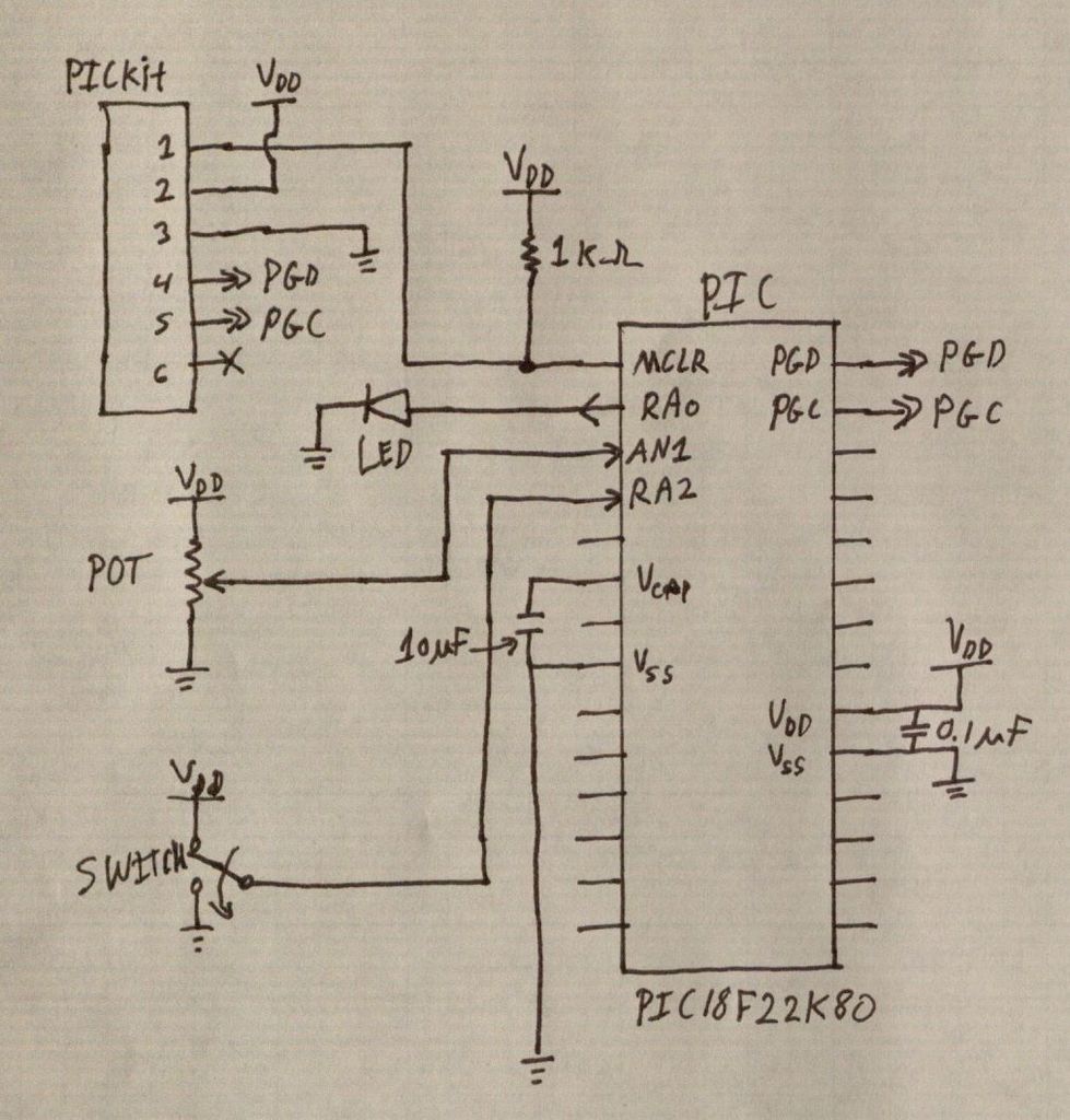
PIC microcontrollers are a highly useful and versatile component for various electronic projects. They are affordable and readily available. PIC microcontrollers are embedded systems that serve as the central control unit in a wide range of electronic applications. Their architecture...
This is a phone bug circuit. This wireless telephone line spy circuit can be used to transmit the phone conversation to a nearby FM radio. This circuit must be... The phone bug circuit is designed to intercept and transmit audio...
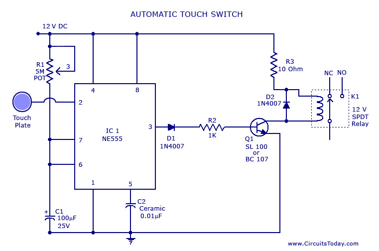
A touch switch circuit schematic utilizing a 555 integrated circuit (IC). When the touch plate is activated, a relay is switched ON for a predetermined duration, which can also be adjusted. The touch switch circuit employs a 555 timer IC...
This is a compact collection of amplifiers configured in a bridge connection. The output power is low, making them suitable for general applications. They can be utilized with small active loudspeakers, car stereos, and similar devices. The only limitation...
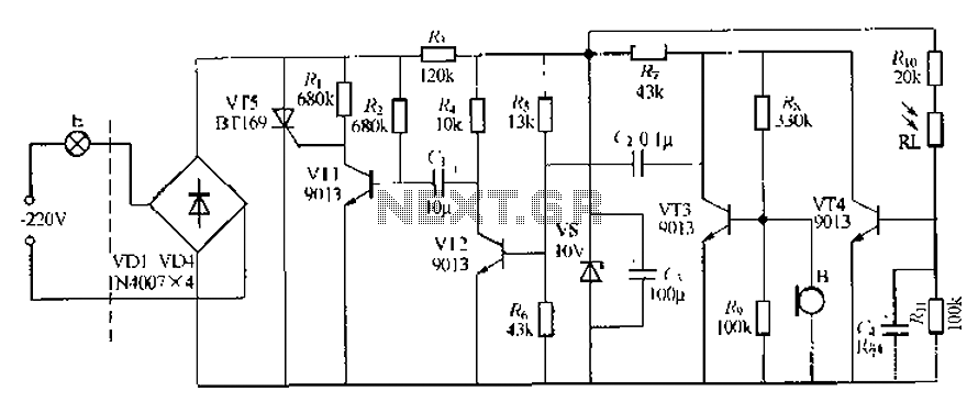
This circuit describes a sound and light control delay system for a walkway stairs light switch. It involves various components including 220V AC electric bulbs, diodes (VD1-VD4), and resistors. The circuit utilizes a rectifier regulator to stabilize the voltage...
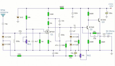
This is a booster antenna circuit designed for frequencies ranging from 550 kHz to 1650 kHz, aimed at amplifying signals received from a telescopic antenna. It covers the medium waveband within this frequency range. To drive low impedance (50...