
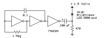
1.5V LED Flasher Circuits
The design of a 1.5 V LED flasher circuit typically involves a few key components: a power supply, an LED, a resistor, and a timing element, which can be a capacitor and a transistor or an integrated circuit (IC). The circuit functions by intermittently powering the LED, creating a flashing effect.
In a basic configuration, a 1.5 V battery serves as the power source. The LED is connected in series with a current-limiting resistor to prevent excessive current from damaging the LED. The timing component, often a capacitor, is charged through a resistor and discharged through the LED, causing it to turn on and off at a specific frequency determined by the values of the resistor and capacitor.
Transistors can be employed to amplify the switching action. For instance, a common NPN transistor can be used to control the LED. When the capacitor charges to a certain voltage, it triggers the transistor, allowing current to flow through the LED and causing it to light up. As the capacitor discharges, the transistor turns off, extinguishing the LED. This cycle repeats, producing a flashing effect.
Alternatively, integrated circuits such as the NE555 timer can be used to create more complex flashing patterns. In astable mode, the NE555 generates a square wave output that can directly drive the LED, providing a reliable and consistent flashing rate.
Overall, these circuits are simple yet effective for applications requiring visual indicators or decorative lighting, and their low power requirements make them ideal for battery-operated devices.Some 1.5 v LED flasher circuits are available on the internet and we like to present you four of them. The flasher circuits below operate on a single 1.5 v.. 🔗 External reference
Related Circuits
All electronic circuits were initially built on breadboards. Once the circuits were operational, they were soldered onto perfboards to create a more durable system. A power board was designed to stack two batteries in series, providing access to a...

I decided to make a commercial surface mount PC board using the LED2 sensor concept. It is quite sensitive and can track to a few degrees of accuracy in bright sunlight. If a blocking shadow is used the accuracy...
The Automatic Forklift System (AFS) is engineered to enhance the safety and efficiency of warehouse stocking processes. Traditional manually operated forklifts pose injury risks to employees. The Automatic Forklift System (AFS) aims to mitigate these hazards. The Automatic Forklift System...
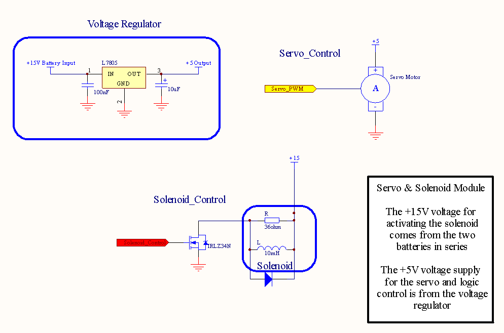
A four-channel DMX512 controlled ringer. The Mk 3 will also incorporate a ringing supply generator, making it reproducible by those without access to the BT ringing supply Number 7. The ringer is microprocessor-controlled, utilizing a Parallax Propeller-based chip, specifically...

This project article was originally written in 2004 when most computers had parallel ports. This is no longer the case, so much of this information is now outdated. The Mini RC Car Project has been one of the most...
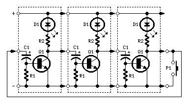
Very simple, versatile modular design. The purpose of this circuit was to create a ring in which LEDs or Lamps illuminate sequentially. Its main feature is a high versatility: you can build a loop containing any number of LEDs...
Warning: include(partials/cookie-banner.php): Failed to open stream: Permission denied in /var/www/html/nextgr/view-circuit.php on line 713
Warning: include(): Failed opening 'partials/cookie-banner.php' for inclusion (include_path='.:/usr/share/php') in /var/www/html/nextgr/view-circuit.php on line 713