
PC Controlled RC Car

To create a cable that connects from the back of the remote's PCB to the computer, a hole must be made in the remote's plastic casing for the wires to pass through. Any size hole will suffice, provided it is large enough for the wires. It is recommended to drill the hole closer to the back of the remote to minimize cable bending. The PCB should be turned over, revealing four solder joints under each button, which are actually two sets of two joints. The wire attached to the negative side of the battery needs to be identified; this will connect to one of the larger green areas on the board. For each switch, two solder joints will be located within this green region and should be left untouched. The focus should be on identifying the positive side of the switch. A wire should be soldered onto each positive side and one wire to any negative terminal (multiple negative terminals are available on the PCB). This will result in one wire per switch being soldered, along with one wire connected to the negative terminal.
Once the wires have been soldered, they should be fed through the previously drilled hole to facilitate reassembly. A male parallel port connector should then be attached with short wires soldered to pins 2, 3, 4, 5, and 23. Pins 2-4 will transmit data (forward, reverse, left, right), while pin 23 serves as ground. It is important to note that for PC-parallel port interfacing, pins 2-9 are easily controlled data pins, and pins 18-25 are all ground. Other pins may have specialized functions that can be utilized creatively. The remaining task involves constructing a circuit using the provided schematic. This requires several small wires, a solder board, and four 2N3904 NPN transistors. The schematic should be printed out and used to build the circuit. It is crucial to connect the ground of the parallel port (pin 23) with the remote's negative terminal, as there is no separate ground.
If the schematic has been followed and the assembly steps completed correctly, the final task is to reattach any wires cut at the beginning and reassemble the components. The previously cut wires should be replaced with longer ones for ease of soldering. Although it is possible to strip the old wires and reconnect them using electrical tape, using longer, new wires is recommended for convenience. After reassembling the remote, all wires should be pressed down flat against the back of the PCB, and the screws should be replaced. The remote may require several attempts to fit properly due to the increased number of wires. Finally, the plastic cover of the remote should be reattached, and the screws secured at the back.
The project involves interfacing a mini RC car with a computer via a parallel port connection. The essential components include the remote control's PCB, a male parallel port connector, and several NPN transistors to control the motors. The schematic outlines the necessary connections for controlling the car's movement, with the transistors acting as switches to modulate the power supplied to the motors based on the input signals received from the parallel port. Proper soldering techniques and careful assembly are critical to ensure functionality and reliability in the final product.This project article was originally written in 2004 when most computers had parallel ports. This is no longer the case, so much of this information is now outdated. The Mini RC Car Project has been one of my favorites to do. If you haven`t checked that project out, please read through that one before starting on your own. I`ve gotten a few e-mails requesting a guide and since the software is done, all that is required is to construct the hardware. This is the second time I`ve done this project, using totally two completely different cars. The remote PCBs (electronics) were almost identical in both, so I`m assuming most all mini rc remotes are very similar, so this guide should be able to apply to all makes and models.
In order to get a cable that goes from the back of the remote`s PCB to the computer, we need to make a hole in the remote`s plastic case for the wires to go through. Any size hole will do, as long as it`s big enough for your wires to fit through. Drill the hole closer to the back of the remote, if possible. That just makes it so the cable won`t have to bend as much. Turn over the PCB (printed circuit board). Under each button there are four solder joints. These are actually (2) sets of (2) joints. These are highlighted in the picture on the right. Identify the wire that the negative side of the battery was connected to (see wire indicated in the picture).
This will connect to one of the large green areas on the board. For each switch, two of the solder joints will be located in this green region. Leave those joints alone. What we are concerned with, is the positive "side" of the switch. For each switch, you need to identify which side is negative and which is positive. Solder a wire onto each positive side and one wire to a negative terminal (there are many negative terminals on the PCB, it doesn`t matter which you choose). You should have 1 wire per switch soldered, and one wire to the negative terminal. My board, with the wires soldered can be seen to the left. Boxes are drawn in to show the same groups of four shown above. Before you start building the cable, feed the wires you soldered, through the hole you drilled earlier.
This will allow you to put it all back together again at the end. Take the male parallel port connector and solder short wires to pins 2, 3, 4, 5, 23. Pins 2-4 will carry the data (forward, reverse, left, right) and pin 23 is ground. Side note: when doing any pc-parallel port interfacing, pins 2-9 are easily controlled data pins and pins 18-25 are all ground. Other pins have specialty functions and can be used in interesting ways. The rest consists on building a circuit, using the schematic (diagram) I have made up. For this you need, a bunch of small wires, solder board, (4) 2N3904 NPN Transistors. Print out the schematic below and build the circuit. (Note: the ground is the Parallel Port Pin 23 and Remote Negative Terminal connected together, there is no `third` ground.
) If you`ve followed the schematic and completed the following steps properly, all we have left to do is re-attach the wires cut at the beginning and put everything back together. In the first step, you cut some wires. Those will now need to be re-attached. I would suggest replacing them with your own wires and use longer ones. The factory wires are very cheap and it`s a lot easier just to use wires double as long, so you have enough room to solder them to where the old wires use to be.
You can always just strip the old wires are re-attach using electrical tape, but I think my way is easier. The choice is up to you. The remote needs to be re-assemled. Squish down all the wires down on the back of the PCB and put the screw back in. It might take several tries to get it flat enough, because there`s a lot more wires back there than there use to be.
Put back on the plastic remote face and replace the screws in the back of the remote. The remote should look very m 🔗 External reference
Related Circuits
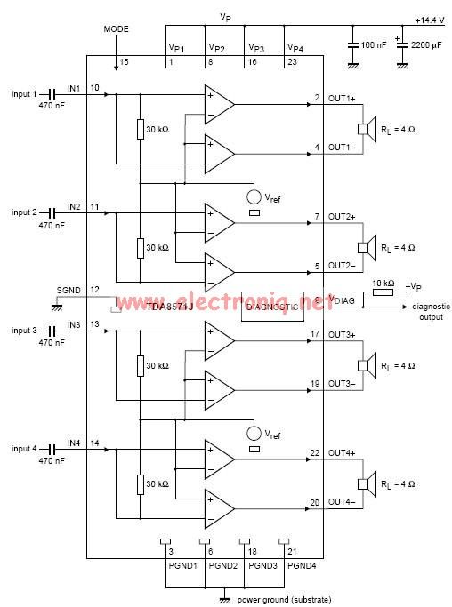
This electronic circuit diagram represents an audio power amplifier utilizing the TDA8571J integrated circuit. It is a class-B output amplifier configured in a BTL (Bridge-Tied Load) arrangement, featuring four amplifiers, each with a gain of 34 dB. The main...
The 567 IC tone decoder/detector can be utilized to construct a remote control or intercom system. This circuit is capable of controlling a relay or transmitting an audio signal. The 567 IC is a versatile component often employed in tone...
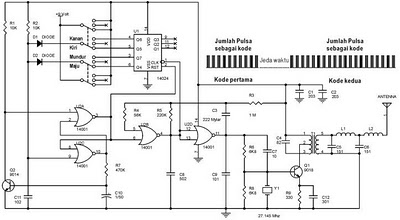
The following circuit illustrates a schematic diagram for a remote control toy car. Features: it does not interfere with the performance of the original design. The remote control toy car circuit typically consists of several key components that enable wireless...
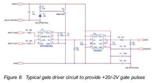
The silicon carbide (SiC) MOSFET offers notable advantages, including a straightforward drive circuit. It possesses unique characteristics that render it a superior switching device in comparison to traditional options. The silicon carbide MOSFET is a type of field-effect transistor that...
In today's world, owning a car battery charger at home has become essential. Having one readily available can help prevent starting issues caused by battery problems. While purchasing a commercial battery charger can be expensive, the components required for...
An LMX1601 Phase locked loop, a discreet FET VCO, and an AVR microcontroller combine to make a stable, easy to use monophonic FM transmitter that includes an audio activated switch that turns the transmitter on only when it is...