
Furby robot using PIC16F819

The redesigned Furby circuit board integrates a PIC16F819 microcontroller at its core, which serves as the primary control unit for the device. This microcontroller is responsible for managing the various functionalities of the Furby, including the sequential movement of the eyes, mouth, and ears, which is accomplished through a single motor. The motor's operation is finely tuned by utilizing a FAN8200 H-Bridge motor driver, enabling precise control over the motor's direction and speed.
The system includes two essential sensors derived from the motor's servo mechanism. The first sensor generates approximately 200 pulses throughout the entire sequence of movements, providing a reliable timing reference. The second sensor, known as the 'index' pulse sensor, is crucial for identifying the start and end points of the movement sequence, ensuring synchronization of the Furby's actions.
In addition to the motor control and pulse sensors, the circuit incorporates a variety of other sensors to enhance interactivity. These include multiple switches, an infrared (IR) sensor, a photo sensor for light detection, and a microphone for sound input. The outputs from the system are directed towards the IR system, motor, and speaker, enabling the Furby to respond to environmental stimuli and produce audio feedback.
Due to spatial constraints on the circuit board, traditional wire-wrapping techniques were deemed impractical. Instead, point-to-point wiring was employed, utilizing clipped segments of #30 wire to establish connections between components. The circuit board was meticulously shaped to match the original Furby design, ensuring compatibility with the existing housing.
The 24LC256 serial EEPROM is utilized for storing audio samples, allowing for the playback of sounds and phrases. The MCP41010 digital potentiometer functions as an 8-bit digital-to-analog converter (DAC), facilitating audio signal processing. The LM386 serves as the speaker driver, amplifying the audio output for clear sound reproduction. An IR LED is included in the design to function as a tachometer sensor, providing feedback on the motor's operation, while a mercury tilt switch is integrated to detect motion and enhance the interactive experience.
While the current software implementation is still in the preliminary stages, initial tests have confirmed the successful operation of key components, including the motor drive, tachometer sensor, index sensor, tilt switch, sound EEPROM, and audio system. The ongoing development aims to explore the full potential of the device, enhancing its capabilities and interactivity.There are several websites documenting the original Furby circuit board. I decided to replace the original circuit entirely and replace it with a PIC based controller. The mechanism of the Furby itself was designed around micro- controllers. It has one motor that runs the eyes, mouth, and ears in sequence. Two sensors are provided from the motor servo system: one counts off about 200 pulses for the entire sequence, the other is an 'index' pulse that lets you find the start/end of the sequence. Several other sensors are provided including several switches, IR sensor, photo sensor, and microphone.
The outputs are to the IR system, motor, and speaker. A circuit board was cut to a size and shape of the original board. Because of space limitations, wirewrapping was not possible. Point to point wiring using clipped pieces of #30 wire was done by hand. The basic circuit uses-- PIC16F819 microcontroller, FAN8200 H-Bridge (motor driver), 24LC256 serial eeprom (for audio samples), MCP41010 digital potentiometer (used as 8-bit D/A), LM386 speaker driver, IR led (for tachometer sensor), and a mercury tilt switch to sense motion. The current software is rudimentry at this time and will be provided later. So far, the motor drive, tachometer sensor, index sensor, tilt switch, sound eeprom, and audio system have all checked out.
This is one of those ongoing projects to see just how smart (wierd) this device may become. 🔗 External reference
Related Circuits
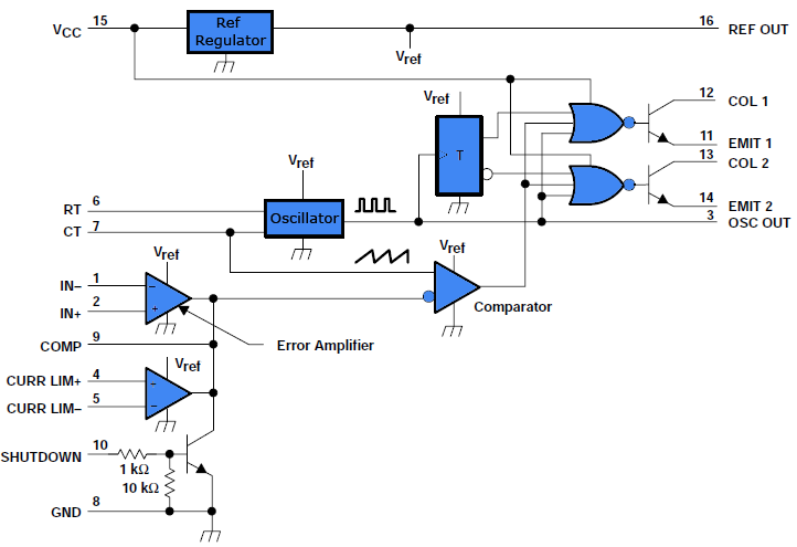
This document outlines a simple PWM (Pulse Width Modulation) DC to AC voltage inverter circuit based on the SG3524 integrated circuit. The SG3524 is a fixed frequency PWM voltage regulator control circuit that offers indifferent outputs suitable for both...
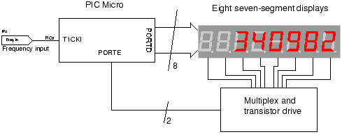
The circuit employs a straightforward approach for direct frequency measurement, which is user-friendly but results in the number of displayed digits varying with the input frequency. To consistently display all digits, a method known as reciprocal counting can be...
A novice in circuit creation is utilizing a 12V battery regulated to 2mA with an LM334Z current regulator. Documentation for the current regulator is available. The LM334Z is a versatile current regulator that can be used in various applications requiring...

This design circuit functions as an alarm system controlled by a keypad. The core component of the circuit is a single transistor from the BC547 series. The circuit requires a 12-key pad, which has 13 terminals; a matrix type...
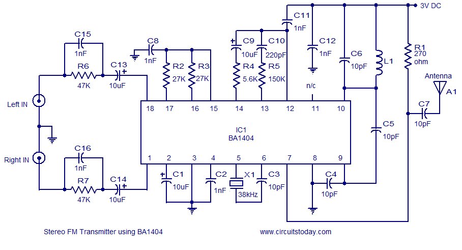
A simple and high-quality FM transmitter circuit designed based on the BA1404 IC. This FM transmitter circuit can be operated from a 3 V battery. The FM transmitter circuit utilizing the BA1404 integrated circuit (IC) is engineered for simplicity and...
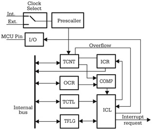
Although there are significant variations between different implementations of the general-purpose timer in various microcontrollers, many similarities exist in the principles of operation and the structure of the timer subsystem. The central element of the timer subsystem is a...