
1.5V Light emitting diode flasher circuit

The circuit utilizes the LM3909, a popular LED flasher IC known for its low power consumption and efficiency in driving LEDs. The IC operates with a supply voltage of 1.5V, making it suitable for battery-powered applications. The NSL5027 is a light-emitting diode that can be effectively driven by the LM3909, providing visible illumination.
The 300μF electrolytic capacitor plays a crucial role in determining the flashing frequency of the LED. In this configuration, the capacitor is connected to the timing circuit of the LM3909, which controls the on-off cycling of the LED. The capacitance value, along with the resistive components in the circuit, sets the flash rate to approximately 1Hz, meaning the LED will blink once per second.
To achieve this, the LM3909 uses an internal oscillator that charges and discharges the timing capacitor. When the capacitor charges to a certain voltage, the IC switches the output to turn on the LED. As the capacitor discharges, the LED turns off, completing one cycle of the flashing process. The choice of a 300μF capacitor allows for a relatively slow charge and discharge rate, resulting in the desired 1Hz flash rate.
This circuit is ideal for applications that require a simple and efficient LED flashing solution, such as indicator lights, decorative lighting, or signaling devices. The combination of a low-voltage supply, efficient LED, and well-chosen timing capacitor makes this design both effective and practical for various electronic projects.Withthe 1.5V battery supply power, The Integrated circuit LM3909 can drive the light emitting diode NSL5027. The 300uF electrolytic capacitor is circumscribed capacitor? which makes the flash speed limit around 1Hz.. 🔗 External reference
Related Circuits

This circuit counts the flashes of turn signals. After approximately 70 flashes, a chime sounds to remind the driver to deactivate the turn signal. The period can be altered by using different taps on U2 if desired. BZ1 serves...

This small device can be aimed at a television to jam the remote control signal. The circuit design is straightforward. A 555 timer is configured as an astable multivibrator operating at a frequency of approximately 38 kHz, which is...

Light Sensitive Staircase Switch with Triac. The operation of the third circuit is quite similar, except that it incorporates photo sensitivity. The circuit is illustrated in the schematic. When there is insufficient light... The light-sensitive staircase switch circuit utilizes a...
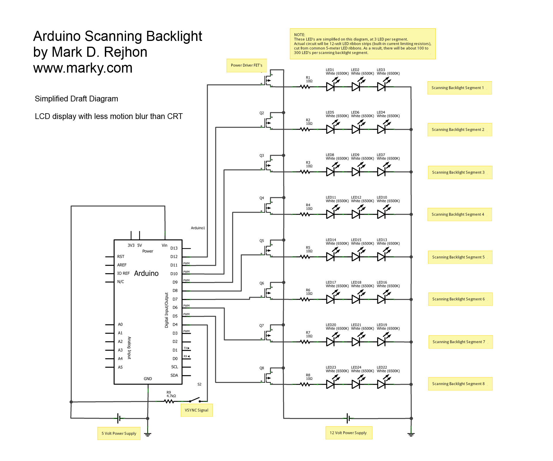
This is a simplified schematic diagram for a homemade scanning backlight driven by an Arduino, an open-source electronics prototyping platform. The Arduino monitors the VSYNC signal (input-lag compensated) and executes a backlight scanning sequence, using ultra-short strobes of super...
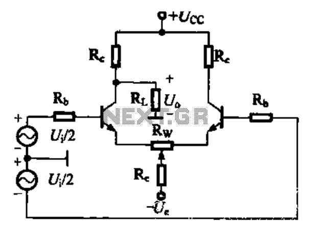
A comparison of four connection methods and features of a differential amplifier circuit is presented. The circuit demonstrates a magnification of a single tube with half the earnings, effectively countering common-mode negative feedback effects. The Common-Mode Rejection Ratio (CMRR)...

The power controller operates from the vehicle's accessory switch, allowing the load to receive power only when the ignition key is in the "on" position. A momentary pushbutton controls a load of up to 10 A using half of...