
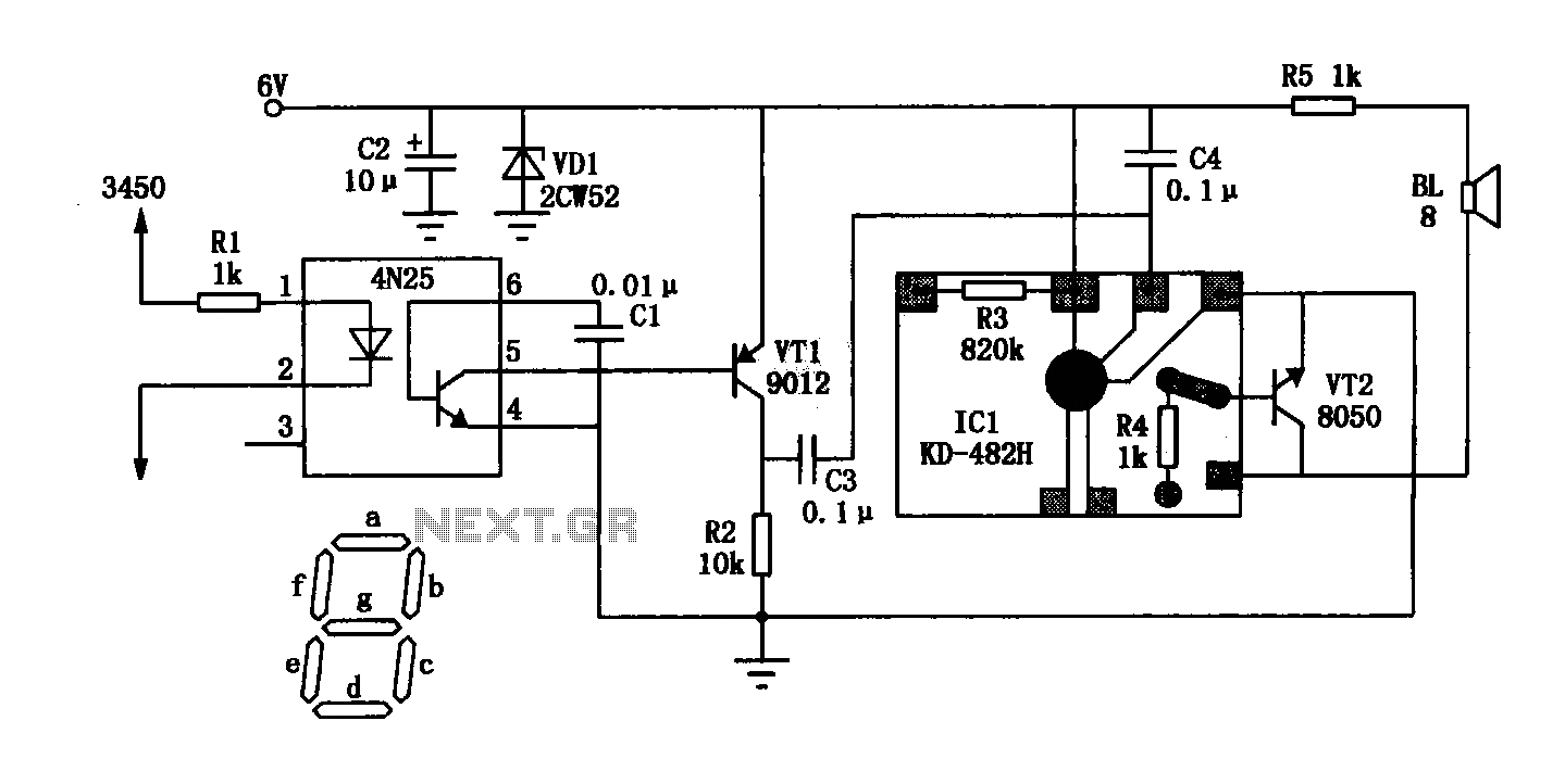
TV remote control blocker/jammer circuit diagram

The described circuit utilizes a 555 timer integrated circuit (IC) in an astable configuration, generating a continuous square wave output. This output is at a frequency of approximately 38 kHz, which is critical for effectively jamming the IR signals from standard remote controls. The 555 timer's duty cycle can be adjusted by varying the resistances connected to pins 6 and 2, as well as the capacitor connected to pin 3, allowing for fine-tuning of the output signal.
The transistor in the circuit is used to amplify the current supplied to the infrared LEDs. By providing around 25 mA, the circuit ensures that the emitted IR light is strong enough to interfere with the remote control signals. Adjusting the resistor value will affect the current through the LEDs, thus influencing the range of the jamming effect. A lower resistance value increases the current and, consequently, the intensity of the emitted IR light, enhancing the range of the device.
The 10K potentiometer allows for real-time adjustments to the jamming frequency or intensity while the device is aimed at the television. This is crucial, as the effectiveness of the jamming can vary based on the specific remote control and television model. The trial-and-error method mentioned is a practical approach to find the optimal settings for the device to ensure that the remote control commands are effectively blocked.
It is important to note that the information provided is intended for personal use only, and any commercial application of this circuit should be approached with caution and requires prior permission from the authors of the original material. Additionally, the content is provided without guarantees, and users should be aware of potential copyright issues when utilizing or reproducing this information.Just point this small device at the TV and the remote gets jammed. The circuit is self explanatory. 555 is wired as an astable multivibrator for a frequency of nearly 38 kHz. This is the frequency at which most of the modern TVs receive the IR beam. The transistor acts as a current source supplying roughly 25mA to the infra red LEDs. To increas e the range of the circuit simply decrease the value of the 180 ohm resistor to not less than 100 ohm. It is required to adjust the 10K potentiometer while pointing the device at your TV to block the IR rays from the remote.
This can be done by trial and error until the remote no longer responds. Disclaimer: All the information present on this site are for personal use only. No commercial use is permitted without the prior permission from authors of this website. All content on this site is provided as is and without any guarantee on any kind, implied or otherwise. We cannot be held responsible for any errors, omissions, or damages arising out of use of information available on this web site.
The content in this site may contain COPYRIGHTED information and should not be reproduced in any way without prior permission from the authors. 🔗 External reference
Related Circuits
Due to the low coupling coefficient, the primary self-inductance tends to short out the driving signal. However, utilizing a series/parallel set of capacitors for energy coupling increases the input impedance at resonance, thereby achieving good power transfer efficiency. The...
The anatomy of two ignition experiments revealed a common issue, specifically that both ends of the ignition coil are equipped with a diode. This design choice by manufacturers has implications for performance. The ignition coil generates a negative half-cycle...
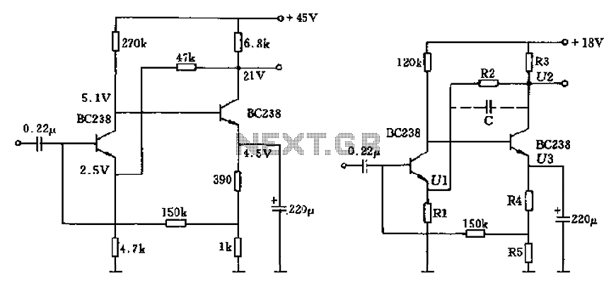
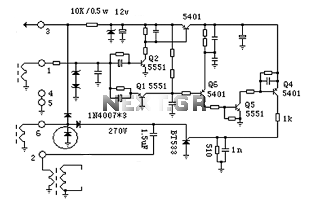
The circuit characteristic involves the elimination of external input resistors, which reduces the influence on the stabilization of the working point. It also employs two DC negative feedback loops. Additionally, the output from the second stage connects to the...
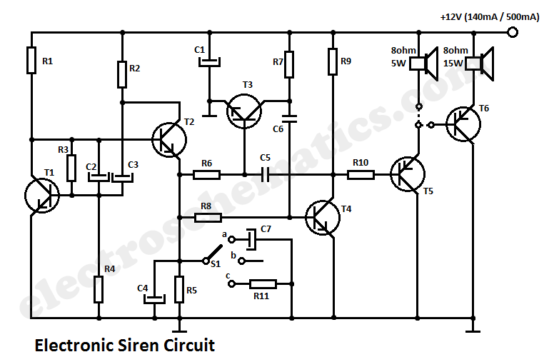
This circuit generates a tone that resembles a siren. The generator section consists of a combination of PNP and NPN transistors that form a free-running multivibrator. If capacitor C2 were connected to the positive line of the power supply,...
The General Dynamic LED digital clock lacks a timekeeping function, but by adding a simple circuit, it can incorporate this feature. The integrated circuit (IC) includes a programmable mute function, which is inactive from 23:00 to 5:00 to avoid...
This compact video transmitter is highly effective for short-distance video surveillance, operating efficiently up to 100 meters. It can be paired with either a black-and-white or infrared camera module, providing excellent image quality on standard color or black-and-white televisions....