
1.5V miniature wireless FM microphone circuit

The wireless FM microphone circuit is designed to operate efficiently with a minimal component count, making it suitable for various applications such as public speaking, musical performances, and broadcasting. The core of the circuit consists of a high-frequency oscillator, formed by the transistor BG1 and the capacitors C1 and C3. This oscillator generates the carrier frequency that is modulated by the audio signal captured by a microphone.
The choice of components is critical for ensuring stable operation and optimal performance. BG1, typically a low-power transistor, acts as the main amplification element, allowing for the modulation of the audio signal onto the carrier frequency. Capacitors C1 and C3 are essential for tuning the oscillator to the desired frequency and for filtering purposes, ensuring that the output signal remains clean and free from unwanted noise.
The circuit's transmission range is directly affected by the power supply voltage. Operating at 6V enhances the circuit's performance, allowing for a greater transmission distance, which can exceed 100 meters under ideal conditions. Additionally, the circuit may include a power amplifier stage to further increase the output signal strength, thereby improving the range and clarity of the transmitted audio.
Overall, this miniature wireless FM microphone circuit exemplifies an effective design that balances simplicity with functionality, making it an excellent choice for applications requiring reliable wireless audio transmission.The circuit shown in this paper uses 12 components to form a miniature wireless FM microphone with stable operating frequency, and its transmitting distance is about 30 meters and more than 100 meters at 6V power supply.The circuit is shown as Figure, BG1, C1 and C3 form a high - frequency oscillation circuit. The transmitting distance is related to the curr.. 🔗 External reference
Related Circuits
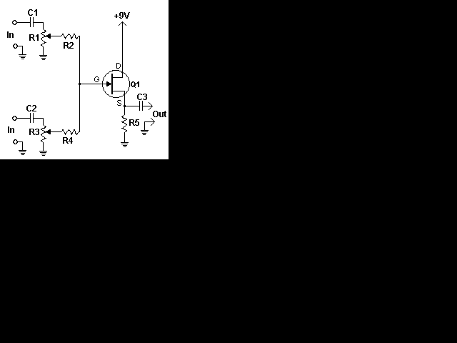
This simple circuit combines two or more audio channels into a single channel (for example, converting stereo to mono). The circuit is capable of mixing any number of channels and operates with minimal power consumption. While the schematic illustrates...

The light-sensitive CDS cell R8 is configured in a bridge circuit with IC1 functioning as a comparator. When light strikes the CDS cell R8, the output of IC1 goes high, triggering SCR1. This action illuminates LED1 and activates opto...
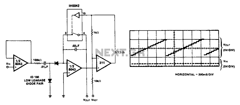
This simple circuit utilizes an LM311 as a level detector, incorporating CMOS analog switches to control capacitance. A significant feature of this counter is its ability to change numbers. The comparator operates more efficiently when there is a need...
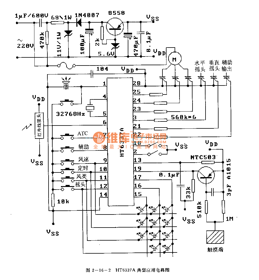
The HT6337 is an infrared remote control receiving decoder circuit specifically designed for electric fan applications. It is housed in a 28-pin dual-row DIP package, with the compatible model being HT12C. The HT6337 is part of a series of...
The high durability of a light-emitting diode (LED) makes it suitable for ON/OFF indicator applications. However, there are limitations regarding low operating voltage. Light-emitting diodes (LEDs) are semiconductor devices that emit light when an electric current passes through them. Their...
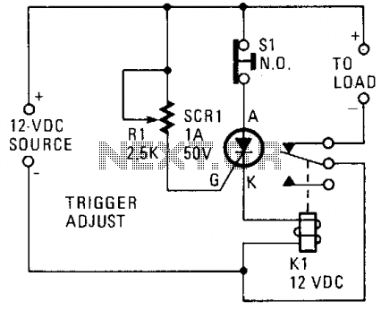
A silicon-controlled rectifier (SCR) is connected in parallel with the 12-V line and linked to a normally-closed 12-V relay, designated as K1. The gate circuit of the SCR is utilized to monitor the applied voltage. While the applied voltage...