
1 Second Time Base From Crystal Oscillator

The circuit employs a crystal oscillator that generates a stable frequency, which is essential for timekeeping applications. The use of CD4040 counters allows for versatile division of the input frequency to achieve a precise output. The selection of the crystal frequency is critical; for instance, a 50 kHz crystal enables a straightforward division to achieve a 1-second pulse. The design also considers the cascading of two 12-stage counters to create a 24-stage binary counter, which provides flexibility in selecting the appropriate bits for output.
In scenarios where the crystal frequency is not an even multiple of two, additional components are necessary to maintain the integrity of the timing signal. The gating of specific bits ensures that the correct count is reached before a reset pulse is issued. The Schmitt Trigger inverter plays a crucial role in generating a clean reset pulse, which is necessary to avoid any potential timing errors caused by insufficient pulse width.
The choice of resistor and capacitor values in the reset circuitry is also significant. The 47 kΩ resistor and 470 picofarad capacitor work together to create a time constant that sustains the output during the reset process. This ensures that the counters return to a known state without introducing significant timing errors, especially at higher frequencies where the timing becomes more critical.
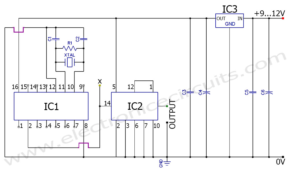
Overall, the design effectively balances precision, stability, and reliability, making it suitable for applications requiring accurate timing signals derived from crystal oscillators. The careful consideration of component values and circuit topology contributes to the overall performance of the timing circuit.The schematic below illustrates dividing a crystal oscillator signal by the crystal frequency to obtain an accurate (0. 01%) 1 second time base. Two cascaded 12 stage counters (CD4040) form a 24 stage binary counter and the appropriate bits are gated together to produce the desired division.
Using a crystal of some even multiple of 2 is desirable s o that one stage of the counter automatically toggles every second which eliminates the need for the NAND gate and reset circuitry, however the circuit below illustrates using a crystal which is not an even multiple of 2 and so requires additional components. Using a 50 Khz crystal, a count of 50000 is detected when the appropriate counter bits that add up to 50000 are all high.
This corresponds to bits 15 (32768) + 14 (16384) + 9 (512) + 8 (256) + 6 (64) + 4 (16). Bits 14 and 15 are the 3rd and 4th stages of the second counter, bit 0 is the first stage of the first counter (Q1, pin 9). To use a 100 Khz crystal, each bit would be moved one to the right so the total would be (65536 + 32768 + 1024 + 512 + 128 + 32 = 100, 000).
Using a 1 Mhz crystal, the following bits would be needed: At 1 Mhz, the 330K resistor in the oscillator circuit will need to be reduced proportionally to about 15K. When the terminal count is reached, a 7 uS reset pulse is generated by the Schmitt Trigger inverter stage that follows the NAND gate.
The 47K resistor and 470 picofarad capacitor sustain the output so that the counters are reliably reset to zero. This is less than one clock cycle at 50Khz and does not introduce an error but would amount to 7 cycles at 1 MHz which would cause the counters to lose 7 microseconds of time per second.
It`s not much of an error (7 parts in a million) but it would be there. The minimum reset pulse width for the 4040 CMOS counters is about 1. 5 uS, so the reset pulse cannot be made much shorter. 🔗 External reference
Related Circuits
The Birmingham, Alabama Crystal Radio Group website serves as the host for the crystal radio receiving contest. This page provides information about the group and its activities related to crystal sets, including details about the 2008 contest radios. The Birmingham,...
Time delays ranging from 0 milliseconds to over three minutes can be achieved with this circuit without the need for tantalum or electrolytic capacitors. The timing interval begins when power is applied to the circuit. At the conclusion of...
Introduction The MIC2290 is an internally compensated standard step-up switching regulator that features an integrated power switch and Schottky diode. The inclusion of these components makes the MIC2290 an optimal solution for 48V Avalanche Photo Diode (APD) applications. In...
The circuit was designed to create an alarm system that alerts a sleeping person to prevent snoring by utilizing a vibrator instead of an audio alert. The circuit operates on the principle of detecting snoring sounds through a microphone or...
This timer was designed for people wanting to get tanned but at the same time wishing to avoid an excessive exposure to sunlight. A Rotary Switch sets the timer according to six classified Photo-types. A Photo resistor extends the...
A frequency generator circuit capable of producing 50 Hz and 60 Hz outputs using a crystal oscillator. This oscillator can be utilized to generate precise frequency signals. This frequency generator circuit employs a crystal oscillator as its core component, which...