
50Hz 60Hz Frequency Generator Circuit Using Crystal Oscillator

This frequency generator circuit employs a crystal oscillator as its core component, which ensures high stability and accuracy in frequency generation. The circuit is designed to provide selectable output frequencies of 50 Hz and 60 Hz, making it suitable for various applications, including timing circuits, signal processing, and synchronization tasks.
The crystal oscillator operates at a specific resonant frequency determined by the physical characteristics of the crystal used. In this circuit, additional components such as resistors, capacitors, and possibly a flip-flop or a counter may be incorporated to divide the oscillator frequency down to the desired output frequencies.
For instance, if the crystal oscillator operates at a fundamental frequency of 8 MHz, a series of frequency dividers can be used to achieve the necessary division ratios to produce the target frequencies. A common approach is to use a binary counter that divides the input frequency by 160, resulting in a 50 Hz output, or by 133.33 for a 60 Hz output.
The output stage of the circuit may include a buffer or an amplifier to ensure adequate signal strength for driving loads or interfacing with other circuitry. Careful consideration should be given to the power supply requirements, as well as the output impedance, to ensure compatibility with connected devices.
Overall, this frequency generator circuit represents a versatile solution for generating low-frequency signals with high precision, leveraging the inherent stability of crystal oscillators.50 Hz 60 Hz frequency generator circuit using crystal oscillator You can generate 50Hz or 60Hz using this frequency generator. This oscillator.. 🔗 External reference
Related Circuits
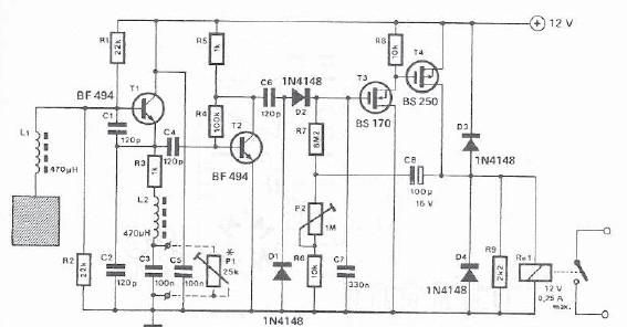
A simple proximity detector can be created using this electronic circuit. This circuit responds to the presence of a conductive object within a specific range. The sensitivity of the circuit can be adjusted with potentiometer P1 to achieve the...
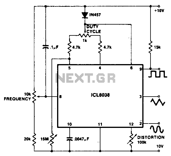
To achieve a 1000:1 sweep range, the voltage across the external resistors Ra and Rb must be reduced to nearly zero. This necessitates that the maximum voltage on control pin 8 surpasses the voltage at the top of Ra...
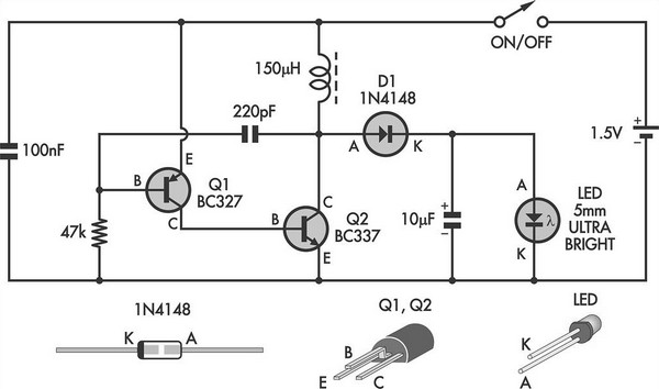
This simple LED torch is powered by a two-transistor blocking oscillator that increases the voltage from a 1.5V cell. It operates based on the inherent current limit. The circuit utilizes a two-transistor configuration to create a blocking oscillator, which is...
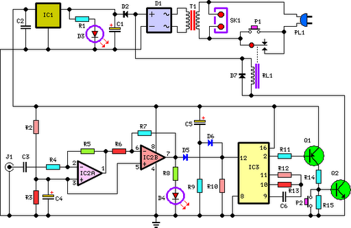
This circuit deactivates an amplifier or any connected device when a low-level audio signal at its input is absent for at least 15 minutes. Pressing P1 turns the device on, supplying power to any appliance connected to SK1. The...
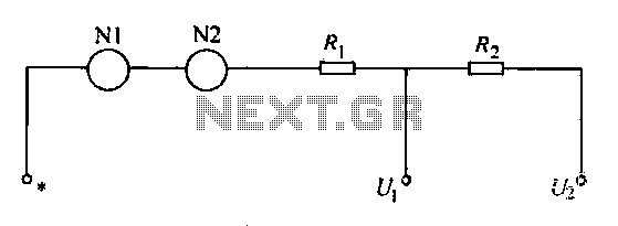
A voltmeter operates through a measuring mechanism in a specified circuit, utilizing a moving coil in series with additional resistance. The fixed coil is denoted as N1, while the moving coil is designated as N2. The additional resistances are...
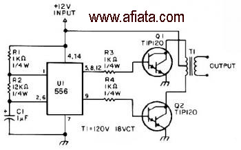
The first section of the 555 timer is configured as an astable oscillator, with R2 and C1 determining the frequency. The output is accessible at pin 5. The second section functions as a phase inverter, with its output available...