
1 watt LED Driver Using a Joule Thief Circuit

The described circuit operates as a Joule Thief, a type of boost converter that efficiently drives a 1-watt LED using a low-voltage power source, such as a single 1.5 V penlight battery. The core component of this circuit is a toroidal ferrite core, specifically a T13 size, which is optimal for minimizing magnetic losses and maximizing inductance.
To construct the inductor, the wire used should be either 0.2 mm or 0.3 mm in diameter, both of which are suitable for creating a robust coil. The winding process involves making approximately twenty turns on each side of the core, ensuring that the turns are evenly spaced to maintain consistent inductance and minimize potential interference between the windings.
The circuit typically includes a small NPN transistor that acts as a switch, rapidly turning on and off to create a pulsed output. This switching action is essential for boosting the voltage from the low input of the penlight cell to a higher voltage suitable for driving the LED. The LED, when connected, will illuminate brightly due to the increased voltage provided by the Joule Thief circuit.
Additional components may include a resistor and a capacitor to stabilize the circuit and improve performance. The resistor is often placed in series with the base of the transistor to limit current and prevent damage. The capacitor can be used to smooth out voltage fluctuations, ensuring a steady output to the LED.
This simple yet effective design is particularly useful in applications where energy efficiency is paramount, such as in battery-powered devices. The Joule Thief circuit exemplifies how low-cost components can be used to create innovative solutions for powering LEDs and other low-power devices.The post explains a simple 1 watt LED driver circuit using a single 1.5 V penlight cell through joule thief concept. The coil may be wound over a T13 torroidal ferrite core using a 0.2mm or 0.3mm super enameled copper wire. About twenty turns on each side will be quite 🔗 External reference
Related Circuits
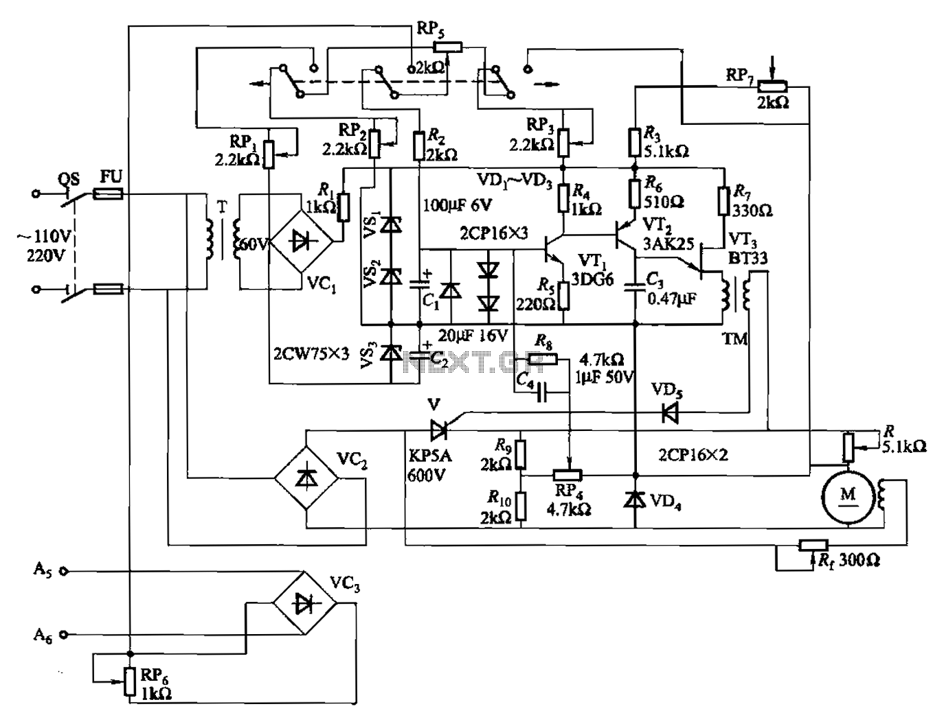
A 100W full-wave single-junction transistor trigger control circuit designed for constant or variable speed control of a wire feed motor. The input control signal consists of a voltage adjusted by the master potentiometer (RPs) and a feedback voltage from...
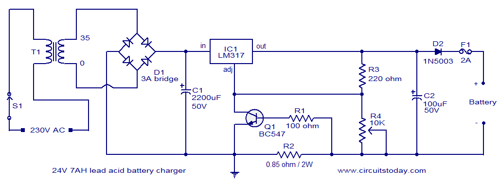
This lead-acid battery charger circuit is designed based on a request from Mr. Devdas C. His requirement was for a circuit that could charge two 12V/7AH lead-acid batteries connected in series. He did not specify the number of cells...

This circuit is for a temperature controlled constant current battery charger. It works with NICD, NIMH, and other rechargeable cells. The circuit works on the principle that most rechargeable batteries show an increase in temperature when the cells become...
This circuit utilizes a JFET to receive signals from an LED and buffer them. The output voltage is managed using an IC 1458 or LM1458, which provides approximately 7 volts in darkness and experiences a drop of about 2...
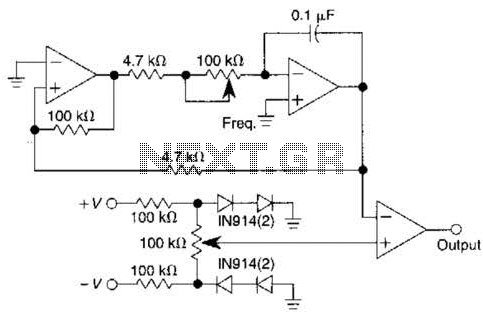
This pulse generator utilizes a single integrated circuit (IC) and six passive components to achieve a frequency range of 400 to 4000 Hz, with an adjustable duty cycle ranging from 1% to 99%. The circuit employs a threshold detector...
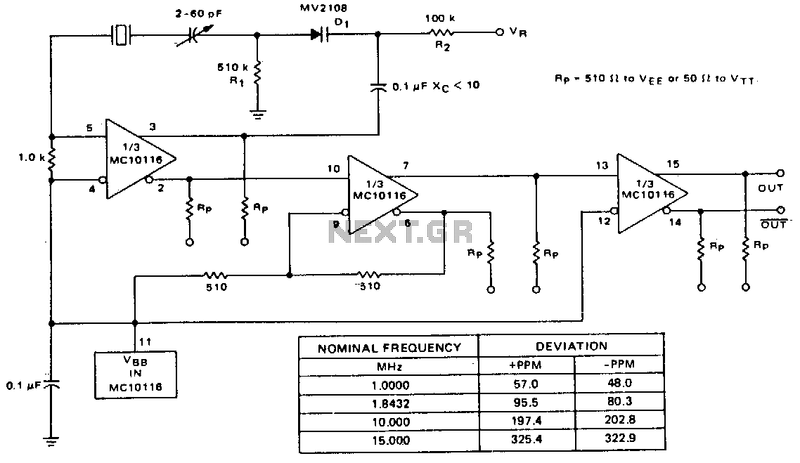
A voltage-variable capacitance tuning diode is connected in series with the crystal feedback path. Adjusting the voltage on the variable resistor (VR) changes the capacitance of the tuning diode, which in turn tunes the oscillator. The 510 kΩ resistor...