
Easy LED Photo Sensor Circuit With LM1458

The circuit employs a Junction Field Effect Transistor (JFET) as the primary signal receiver, which allows for high input impedance and low noise, making it suitable for buffering the signal from the LED. The choice of the IC 1458 or LM1458 operational amplifier is crucial, as it provides the necessary amplification while maintaining stability across varying light conditions.
In operation, when the LED is illuminated by ambient light, the voltage output from the JFET is buffered to prevent loading effects that could distort the signal. The inverting operational amplifier is configured with a gain of 20, which amplifies the buffered signal, allowing for a significant output voltage swing. The circuit is designed to respond to changes in light intensity, providing a range of approximately 5 volts between dark and light conditions.
The inclusion of a 100K potentiometer enables fine-tuning of the output voltage range, allowing users to calibrate the circuit according to specific requirements or environmental conditions. This feature enhances the versatility of the circuit, making it applicable in various light-sensing applications, such as automatic lighting systems or light level indicators. Overall, the design effectively integrates JFET technology with operational amplification to achieve reliable performance in varying lighting environments.This circuit is used J-FET for recieve signal to buffer from LED, About Output voltage, We used IC 1458 or LM1458, while in the dark is about 7 volts and the drop about 2 volts in full sun. The LED voltage buffered by a junction FET transistor and then applied to the input of an operational inverting amplifier with a gain of about 20 minutes.
This is a variation of about 5 volts of darkness and light. You can adjust the 100K potentiometer to set the range of output voltage. 🔗 External reference
Related Circuits
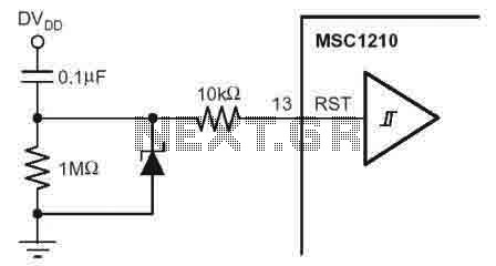
According to the MSC1210 datasheet, you will perform an external reset by taking RST pin high for two tOSC periods as this stops device operation, crystal oscillation, causes all digital pins to be pulled high from that point and...
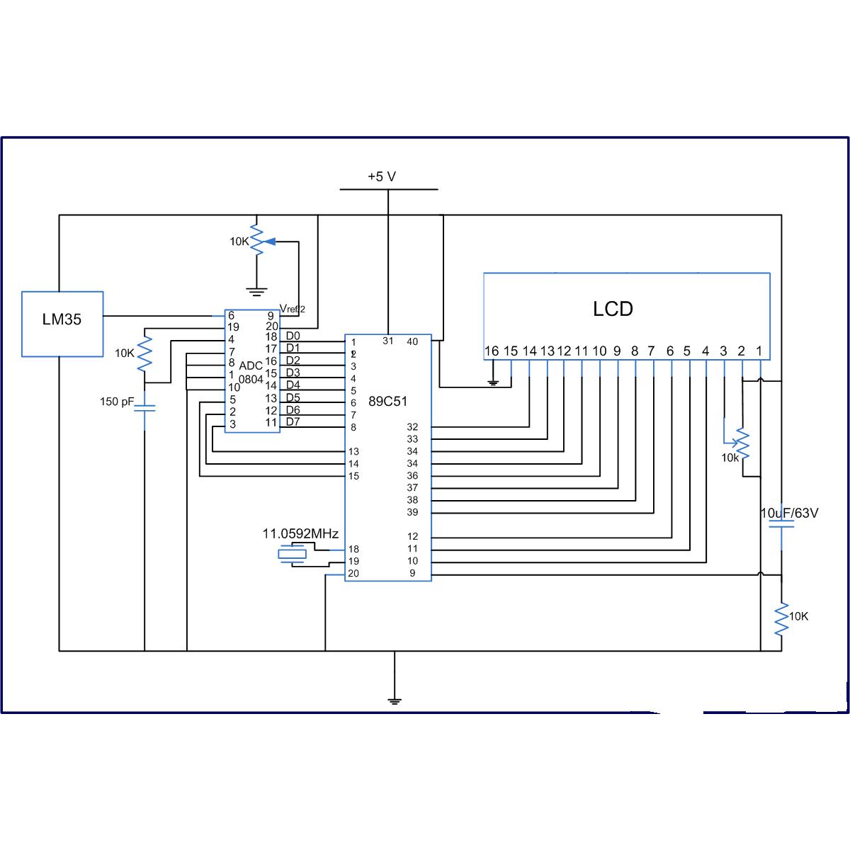
The LM35 series are precision integrated-circuit temperature sensors, whose output voltage is linearly proportional to the Celsius (Centigrade) temperature. The LM35 has an advantage over linear temperature sensors calibrated in Kelvin, as the user is not required to subtract...

Currently, the use of cookers has become fashionable due to their speed, cleanliness, and low pollution levels, making them a favorite among consumers. Cookers circuit. The modern cooker circuit typically involves a combination of heating elements, control systems, and safety...
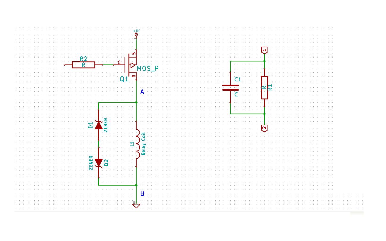
Although this may be a basic question, there is still some struggle with it. In this schematic, two zener diodes D1 and D2 are connected back-to-back across relay coil L1. The breakdown voltage (BVds) is -30V for Q1. The...
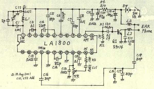
Earphones, batteries are sold separately. AM / FM seems to be a common mold. But stamping is different. AM / FM E193577 UL94V0 board with the AM / FM etching printed circuit board manufacturers are the same. Shape is...

This circuit was first introduced by Signetics Corporation as the SE555/NE555 around 1971. Pin connections and functions are as follows: Pin 1 (Ground) is the most negative supply potential of the device, typically connected to circuit common when powered...