
10.7-MHz IF amplifier

The 10.7-MHz IF amplifier circuit is a crucial component in radio frequency (RF) communication systems, particularly in the demodulation stage of FM receivers and in the final stage of signal processing for cell phone base stations. The design typically involves a combination of transistors, resistors, capacitors, and sometimes inductors, configured to amplify the intermediate frequency signal while maintaining signal integrity and minimizing noise.
Key components of the circuit include a high-gain amplifier, often realized using operational amplifiers or bipolar junction transistors (BJTs). The amplifier is designed to provide sufficient gain to ensure that the weak incoming signals can be processed effectively. The circuit may also incorporate filters to eliminate unwanted frequencies and enhance the desired signal.
Power supply considerations are essential, as the circuit requires stable voltage levels to function optimally. Bypass capacitors are commonly included to filter out noise from the power supply lines, ensuring a clean power source for the amplifier.
In terms of performance metrics, parameters such as gain, bandwidth, input and output impedance, and noise figure are critical for evaluating the circuit's effectiveness. The gain should be sufficient to boost the signal without introducing distortion. The bandwidth must encompass the 10.7-MHz frequency to ensure that the entire signal is amplified without loss.
The layout of the circuit is also vital; careful attention to component placement and routing can minimize parasitic capacitance and inductance, which can adversely affect performance. Shielding may be necessary to protect the circuit from external electromagnetic interference (EMI), which is particularly important in mobile communication applications.
Overall, the 10.7-MHz IF amplifier circuit plays a significant role in modern communication systems, enabling reliable signal processing in various RF applications.This is 10.7-MHz IF amplifier circuit. This circuit is used in many application such as cell phone base station receivers (final IF) and FM broadcast receivers 🔗 External reference
Related Circuits
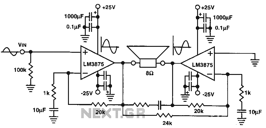
The audio power amplifier delivers 80W of audio power to an 8-ohm load. The LM3875 integrated circuit (IC) requires adequate cooling. It is important to note that in the bridge amplifier configuration, the two connected speakers will produce heat. The...
The preamplifier is designed for use with dynamic (moving coil, MC) microphones that have an impedance of up to 200 ohms and feature balanced terminals. It is relatively straightforward. The preamplifier circuit serves as a crucial interface between the microphone...
The Audio Research Corporation LS22 Line Stage Preamplifier was selected for this upgrade. The Audio Research LS22 Line Stage Preamplifier is a high-performance audio component designed to enhance the quality of sound reproduction in audio systems. This preamplifier features a...
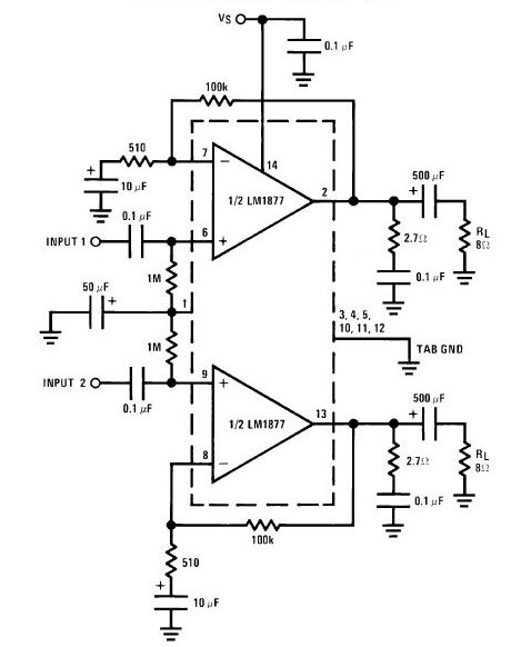
The LA4440 is a dual-channel audio power amplifier integrated circuit (IC) designed for stereo and bridge amplifier applications. In dual mode, it provides significant audio amplification for various audio systems. The LA4440 audio power amplifier is engineered to deliver high-quality...
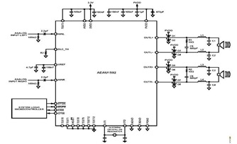
This is a typical stereo application circuit schematic of the ADAU1592, a 2-channel, bridge-tied load (BTL) switching audio power amplifier. The ADAU1592 can be utilized in flat panel televisions, PC audio systems, and mini-component applications. The ADAU1592 is designed to...
This circuit deactivates an amplifier or any other device when a low-level audio signal at its input is absent for at least 15 minutes. By pressing P1, the device is powered on, allowing any appliance connected to SK1 to...