
Stereo Application Circuit Schematic of The ADAU1592 Audio Power Amplifier

The ADAU1592 is designed to deliver high-quality audio amplification in compact applications. It operates in a bridge-tied load configuration, which allows it to drive speakers efficiently by utilizing both output channels to increase the effective output voltage. This configuration enhances power output and improves overall audio performance.
In typical applications, the ADAU1592 can be integrated into various audio systems that require stereo sound reproduction. For instance, in flat panel televisions, the amplifier can be used to enhance the audio experience without the need for external amplification devices. In PC audio systems, it provides sufficient power to drive speakers effectively, ensuring clear and powerful sound output. Similarly, in mini-component systems, the ADAU1592 can be used to maintain a compact design while still delivering robust audio performance.
The circuit schematic typically includes input capacitors to block DC signals, feedback resistors to stabilize the amplifier's gain, and output inductors to filter the high-frequency switching noise. Power supply decoupling capacitors are also included to ensure stable operation and minimize power supply noise. The design may feature thermal protection and overcurrent protection circuits to safeguard the amplifier from damage during operation.
Overall, the ADAU1592 is a versatile and efficient audio amplifier suitable for a wide range of applications, providing high-quality sound reproduction in a compact form factor.This is a typical stereo application circuit schematic of the ADAU1592, a 2-channel, bridge-tied load (BTL) switching audio power amplifier. You can apply ADAU1592 on flat panel televisions, pc audio system and/or mini-components applications
🔗 External reference
Related Circuits
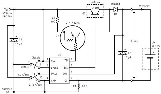
Lithium-ion charger circuit design electronic project using LM3632 controller. The lithium-ion charger circuit utilizing the LM3632 controller is designed to efficiently charge lithium-ion batteries while ensuring safety and longevity. The LM3632 is a highly integrated, step-down linear charger specifically tailored...
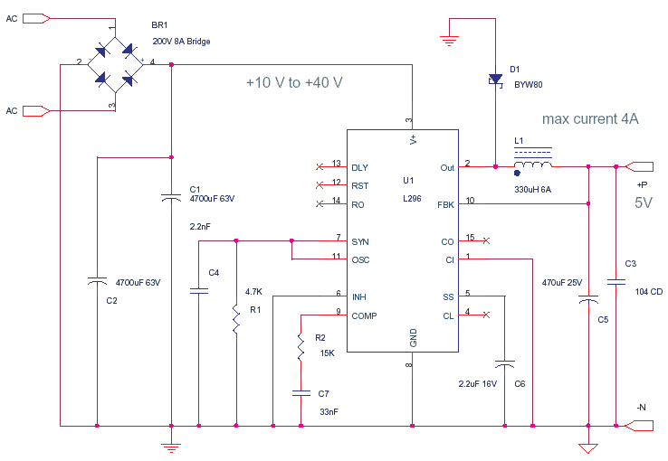
This circuit is based on the application note for the L296, a Power Switching Regulator from ST. The primary benefit of utilizing a switching regulator is the minimal heat dissipation observed in this design. In contrast, implementing a series...
Low-cost water pump controller circuit. The sensors used in the circuit can be any two conductive probes, preferably resistant to electrolytic corrosion. For example, a suitably sealed audio jack can be employed as the sensor. The automatic pump controller...
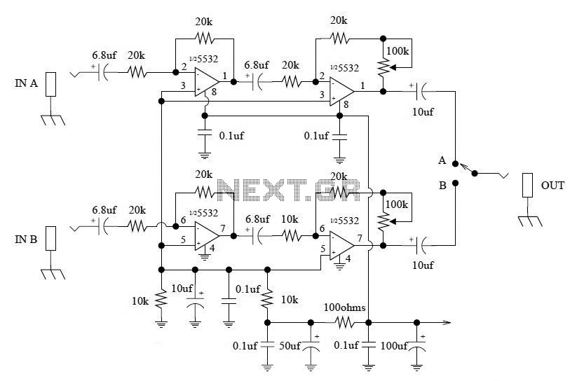
This A/B Box pedal schematic for electric guitar was designed by Rick Barker. The A/B Box effect was originally intended for switching between different harmonica microphones. It features a low-noise dual preamp for improved performance. The A/B Box schematic serves...
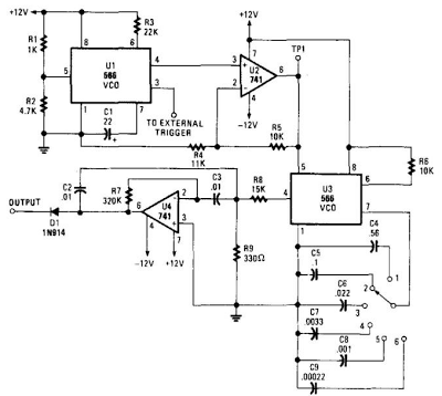
When this circuit is connected to a filter and an oscilloscope, the oscilloscope displays the filter's frequency response. A frequency that sweeps from low to high is applied to a filter. The oscilloscope is triggered by the start of...
This type of design can produce a very high amperage current for a fraction of a second that can be used to do some useful work if properly harnessed. A point to remember is that Paul Baumann built his...