
amplifier timer

This circuit operates as an automatic power management system for devices that rely on audio signals for activation. The core components include operational amplifiers, transistors, and a relay, which work in concert to ensure that the connected devices are only powered when necessary.
The audio signal is processed by IC2, which consists of two operational amplifier stages configured to boost and square the incoming signal. This amplification is crucial for detecting even the faintest audio signals. The LED D4 serves as an indicator, providing visual feedback that the circuit is active and monitoring the input signal.
The timing function is handled by IC3, which is likely a timer IC such as the 555 timer or a microcontroller. It is configured to count the duration of the absence of an audio signal. The reset mechanism, triggered by the brief illumination of LED D4, ensures that any momentary presence of an audio signal will prevent the timer from reaching its 15-minute threshold.
The transistors Q1 and Q2 are configured as a switch to control the relay. When the timer expires and pin 2 of IC3 transitions to a high state, both transistors turn off, which deactivates the relay and cuts power to the connected appliances. This feature is particularly useful for energy conservation, preventing appliances from remaining powered when not in use.
The inclusion of C5 and R9 provides a reset function for IC3, ensuring that the timer starts fresh each time the circuit is powered on. The manual switch P2 allows the user to immediately turn off the circuit, offering flexibility in operation.
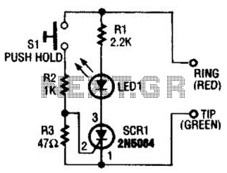
For applications requiring devices that do not utilize standard mains power, the suggestion to use a double-pole relay switch allows for safe and effective control of power to those devices. This configuration ensures that the circuit can be adapted for various operational requirements, making it a versatile solution for audio-activated power management.This circuit turns-off an amplifier or any other device when a low level audio signal fed to its input is absent for 15 minutes at least. Pushing P1 the device is switched-on feeding any appliance connected to SK1. Input audio signal is boosted and squared by IC2 A & B and monitored by LED D4. When D4 illuminates, albeit for a very short peak, IC3 is reset and restarts its counting. Pin 2 of IC3 remains at the low state, the two transistors are on and the relay operates. When, after a 15 minutes delay, no signal appeared at the input, IC3 ends its counting and pin 2 goes high. Q1 & Q2 stop conducting and the relay switches-off. The device is thus completely off as also are the appliances connected to SK1. C5 & R9 reset IC3 at power-on. P2 allows switch-off at any moment. Needing to operate a device not supplied by power mains, use a double pole relay switch, connecting the second pole switch in series with the device`s supply.
🔗 External reference
Related Circuits
The 2SK2975 has reportedly been discontinued by the manufacturer, with the RD07MVS1 from Mitsubishi serving as its replacement. This new device is very similar but appears to have slightly higher gain—10 dB typical at 520 MHz compared to 8.4...
The power supply circuits for servo systems are critical during both the adoption and operational stages. The power supply circuit for servo systems is designed to provide stable and adequate voltage and current levels necessary for the servo motors to...
A friend is interested in building a hi-fi power amplifier, specifically a Class AB model due to its quality sound, particularly in bass response and distinct clarity. This circuit is designed as a hi-fi OCL (Output Capacitor-Less) power amplifier...
Section Ul-a is configured as a high-gain inverting voltage amplifier that is inductively coupled to the phone line via LI. Inductor LI is a homemade unit that consists of 250 turns of fine, enamel-coated wire that is wound on...
This project utilizes the IRF510 MOSFET, a widely available N-Channel enhancement mode power field effect transistor. It is designed to withstand specified levels of energy in breakdown avalanche mode. Unlike bipolar transistors, which are current-controlled and have lower input...
Circuits that utilize large value resistor and capacitor combinations tend to lack accuracy due to the wide tolerance and leakage current of polarized capacitors. A more effective approach is to implement an astable circuit in conjunction with a binary...