
10 Amp 13 8 Volt Power Supply

The circuit is designed to provide a stable and adjustable power supply, characterized by its robust current limiting feature that ensures reliability. The use of three pass transistors necessitates adequate heat sinking to prevent overheating during operation, which is critical for maintaining performance and longevity. Resistor R9 is pivotal in fine-tuning the output voltage; it allows for precise adjustments to achieve the desired voltage level, which can range from 10 to 14 volts. The implementation of a 1K potentiometer for this adjustment enhances user convenience, enabling dynamic voltage changes as required.
The current limiting aspect is managed through a network of resistors (R4 to R7) that effectively regulate the output current. This configuration stands out against conventional designs that often rely on the HFE parameter of transistors. The inherent flaw in such designs is the propensity for thermal runaway, a condition where increased temperature leads to higher HFE, potentially resulting in transistor failure. In contrast, this circuit samples the collector current, allowing for a proactive response to changes in load conditions, thereby minimizing the risk of thermal runaway.
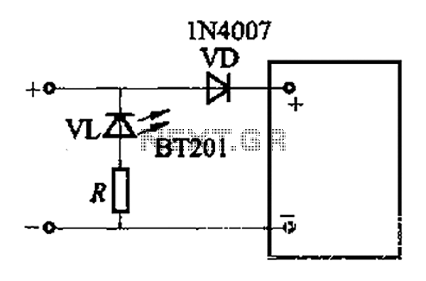
The design also incorporates an optional overvoltage protection mechanism. Although this feature is not essential due to the inherent current limiting design, it provides an additional layer of safety. By connecting an external circuit to Vout, the risk of overvoltage conditions can be mitigated, particularly in scenarios where transistors Q2 or Q3 might fail. The likelihood of a collector-to-emitter short is low, but the design accommodates this possibility, ensuring that the power supply remains robust under various operating conditions.
Overall, this circuit exemplifies a well-thought-out approach to power supply design, prioritizing reliability, user adjustability, and safety.The circuit even has a current limiting feature which is a more reliable system than most commercial units have. The circuit uses 3 pass transistors which must be heat sink. Resistor R9 allows the fine tuning of the voltage to exactly 13. 8 volts and the resistor network formed by resistors R4 through R7 controls the current limiting. The LM723 lim its the current when the voltage drop across R5 approaches. 7 volts. To reduce costs, most commercial units rely on the HFE of the pass transistors to determine the current limiting. The fault in that system is that the HFE of the pass transistors actually increases when the transistors heat up and risks a thermal runaway condition causing a possible failure of the pass transistors.
Because this circuit samples the collector current of the pass transistors, thermal runaway is not a problem in this circuit making it a much more reliable power supply. The only adjustment required is setting R9 to the desired output voltage of anywhere between 10 and 14 volts.
You may use a front panel mounted 1K potentiometer for this purpose if desired. Resistor R1 only enhances temperature stability and can be eliminated if desired by connecting pins 5 and 6 of IC-1 together. Although it really isn`t needed due to the type of current limiting circuit used, over voltage protection can be added to the circuit by connecting the circuit of Figure 2 to Vout.
The only way over voltage could occur is if transistors Q2 or Q3 were to fail with a collector to emitter short. Although collector to emitter shorts do happen, it is more much more likely that the transistors will open up when they fail.
🔗 External reference
Related Circuits
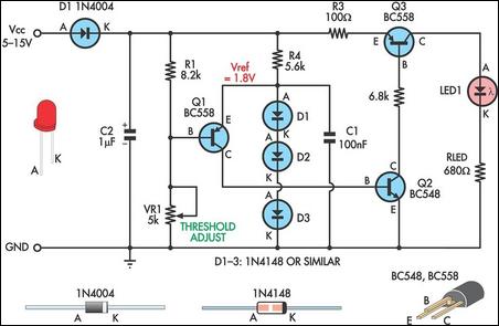
The adjustment potentiometer RP allows for modification of the over-voltage limit setting. In the event of reversed polarity in the DC power supply, there is a risk of damaging equipment components. To mitigate this risk, a reverse polarity protection...
This current-limiting circuit, illustrated as part of a small bench power supply, can be utilized with any dual-rail current source. The section of the circuit on the left limits the current entering the dual voltage regulator (IC4 to IC7)...
An increasing number of devices are being sold that operate on internal rechargeable batteries. While a compatible charger is typically included in the packaging, there are a... Rechargeable battery systems have become prevalent in various electronic devices, necessitating the development...
This is a simple low supply rail detection circuit that is inexpensive and can be assembled in approximately 20 minutes. It operates with low power consumption, making it suitable for integration into battery-powered devices. The circuit utilizes three low-cost...
This battery charger operates by continuously charging at maximum current, gradually tapering off as the battery approaches full voltage. The full load current from the supply transformer and rectifier section is 4.4A. The current decreases to 4A at 13.5V,...
The first essential component for any workshop or lab is a power supply. When experimenting with various electronic circuit designs, having a flexible and adjustable power supply simplifies the process. Presented here is a design for an adjustable power...