
Low Supply Rail Detection

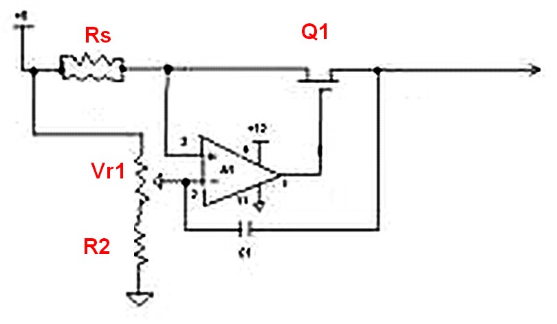
The low supply rail detection circuit is designed to provide a visual indication of supply voltage levels using a simple transistor-based architecture. The circuit's core components include three transistors (Q1, Q2, and Q3), which form a cascade that amplifies the detection of low voltage conditions. The use of diodes D1-D3 to establish a 1.8V reference voltage is critical for ensuring reliable operation, as it sets the threshold for activation of Q1.
The voltage divider created by resistors R1 and VR1 is essential for monitoring the supply voltage. As the input voltage drops, the voltage across the divider also decreases. When this voltage falls below the 1.8V reference, Q1 turns on, allowing current to flow through Q2 and subsequently activating Q3. The output of Q3 is connected to LED1, which serves as the visual indicator. The relationship between the bias current flowing through Q2 and the brightness of LED1 provides a clear, proportional representation of the supply voltage's severity.
The adjustment of trimpot VR1 allows for fine-tuning of the threshold at which LED1 activates, making the circuit versatile for different applications and desired low-voltage levels. The low current consumption of less than 2mA when the LED is off ensures that the circuit is energy-efficient, a crucial characteristic for battery-operated devices.
For applications requiring different operating voltages, the resistor RLED can be calculated to maintain optimal LED performance. This adaptability makes the circuit suitable for a variety of voltage ranges, ensuring its functionality across multiple devices. Overall, this low supply rail detection circuit provides an effective and economical solution for monitoring voltage levels in battery-powered applications.Here`s a simple low supply rail detection circuit that costs peanuts and takes just 20 minutes or so to make. Its power consumption is quite low, so it could easily be built into battery-powered devices. Instead of using an op amp, the circuit is built around three low-cost transistors (Q1-Q3). Diodes D1-D3 form a 1. 8V voltage reference (Vref) for the emitter of Q1. If the voltage across the voltage divider formed by R1 and VR1 is less than this, Q1 turns on and supplies Q2 with base bias current. This turns on Q3 in proportion to this bias current which then drives LED1. The brightness of the LED gives an indication of the severity of the low voltage condition. The brighter the LED, the lower the supply voltage. Trimpot VR1 is adjusted so that LED1 just comes on at the desired low-voltage point. The current consumption is typically less than 2mA when LED1 is off. Finally, the value shown for RLED is suitable for 6-12V operation. For other voltages, RLED can be calculated using the formula RLED = (Vcc 1. 8)/0. 01 (this equates to a current of about 10mA). 🔗 External reference
Related Circuits
All miniature electronic devices operate on batteries. Some require voltages higher than the standard battery voltages for efficient operation. When a battery of the specific voltage is unavailable, it becomes necessary to connect additional cells in series to increase...
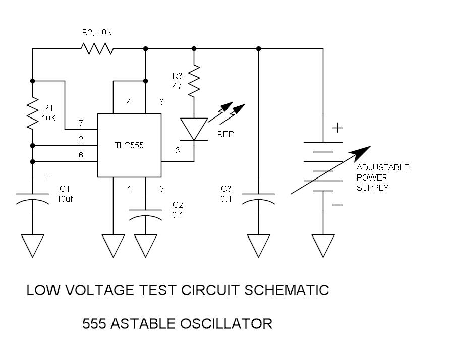
There have been stories regarding the suboptimal performance of the 555 timer IC when operated below a supply voltage (Vcc) of 5V, prompting an investigation into potential improvements for its operation. The 555 timer IC is a versatile device commonly...
The transformer has a 240V primary and has a secondary rated 24V at 2A. The bridge rectifier contains 4 diodes, their current rating needs to be high with respect to the transformers output current; if not the current may...
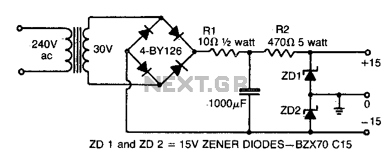
This simple circuit provides both a positive and negative supply from a single transformer winding and a full-wave bridge rectifier. Two zener diodes connected in series create a voltage division, with their junction point grounded. It is important to...
Assuming a 5V output can be achieved after adjusting the potentiometer, will the 240-ohm resistor limit the current, or is there a need to add additional components? If it does limit the current, it is expected that the power...
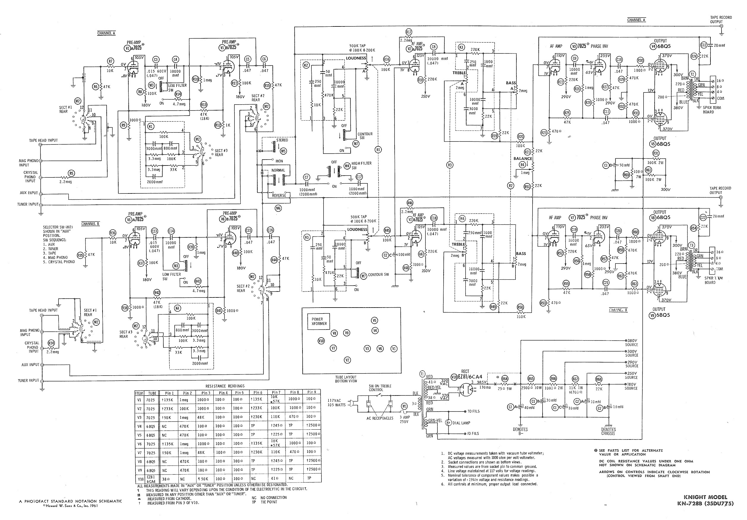
Ty - Concerning the updated schematic of the AF/PI stage, it appears that resistor R45 is not present. Additionally, the disk capacitor bypassing R44 is marked as 68nF750 with a tolerance of 10%, which is presumed to be the...