
One way to prevent reverse polarity of the DC power supply circuit

The described circuit employs an adjustment potentiometer (RP) that serves as a variable resistor, enabling the user to set the desired over-voltage limit for the connected load. This feature is crucial in applications where voltage fluctuations may occur, potentially leading to damage. The reverse polarity protection circuit is essential for safeguarding sensitive components from damage due to incorrect power supply connections.
The circuit operates by integrating a light-emitting diode (LED) VL, which functions as an indicator for the polarity of the power supply. Under normal operating conditions, with the correct polarity applied, the LED remains off, signaling that the system is functioning as intended. When the polarity is reversed, the LED lights up, providing a clear visual indication of the error.
Diode VD plays a critical role in this protection mechanism. It is oriented in such a way that it becomes forward-biased only when the polarity is reversed. In this scenario, VD conducts and effectively shunts the current away from sensitive components, preventing potential damage. This design not only enhances the reliability of the circuit but also provides an intuitive user interface through the LED indicator.
Overall, the implementation of an adjustment potentiometer combined with a reverse polarity protection circuit is a prudent design choice in electronic systems, ensuring both operational flexibility and component safety.Adjustment potentiometer RP, can change the over-voltage limit setting. If the DC power supply polarity is reversed, and there may be burned equipment components, for which pow er can be installed a reverse polarity protection circuit. Circuit shown in Figure 13-91. When the power is properly connected, the light emitting diode VL does not shine. When the power is reversed when, VL lights, and because of the diode VD deadline, to protect the electronic equipment.
Related Circuits
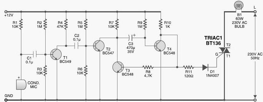
This DIY sound-activated lights circuit turns a lamp on for a brief duration when a dog barks or when a relatively loud sound is detected, creating the impression that the occupants are alerted. The condenser microphone is positioned to...
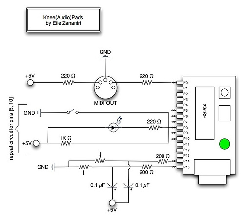
A few nice MIDI controller interfaces were discovered. The Knee(Audio)Pads are a wearable MIDI device. The MIDI controller interfaces mentioned provide innovative solutions for music production and performance. The Knee(Audio)Pads, in particular, represent a unique advancement in wearable MIDI technology....
This circuit consists of two main components: a battery charger that provides a fixed output voltage of 5V DC, and a regulated power supply that allows for an adjustable output voltage ranging from 2 to 9 volts. The circuit design...
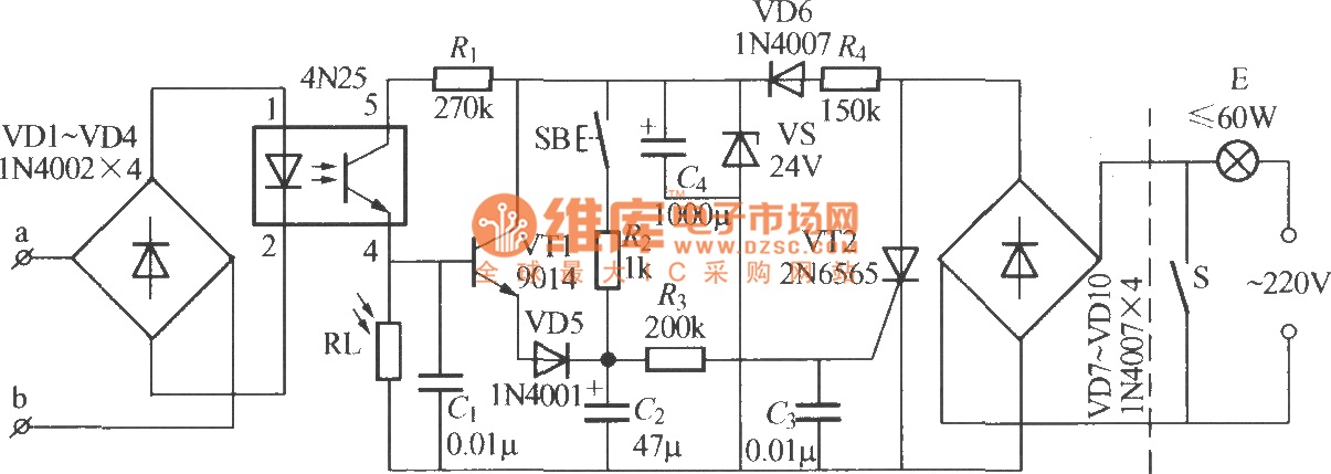
The diagram illustrates an automatic lighting control circuit activated by a telephone. At night, when the telephone rings or the user picks up the receiver, the light turns on. If the telephone stops ringing (when no one is listening)...

This is a 100-watt transistor inverter circuit diagram that features a straightforward design. The circuit utilizes only transistors, eliminating the need for integrated circuits. It converts a 12V battery input into a 220V output with a 50Hz square wave...
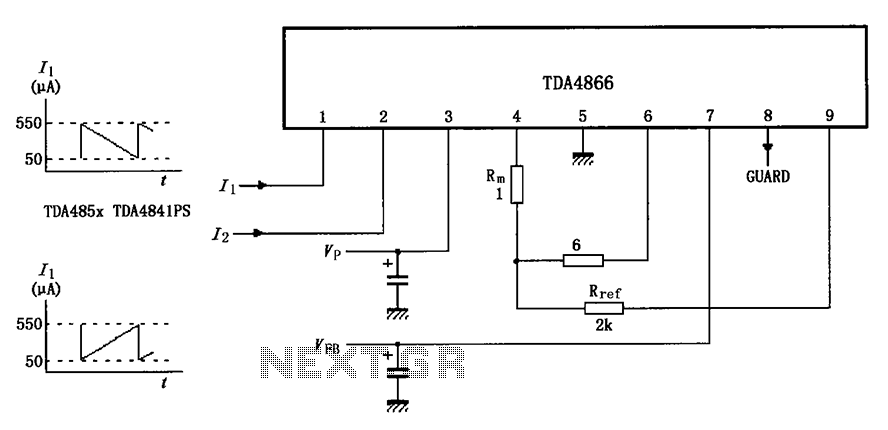
The TDA4866 test circuit operates with a positive supply voltage (VP) and a feedback voltage (VFB) in conjunction with a flyback circuit. The circuit responds to changes in the input signal, transitioning from one state to another. The input...