
10 Band Graphic Equalizer

The circuit for this device should be constructed in two separate pieces, each corresponding to a different channel. The regulation of these channels is controlled by a potentiometer, which should be a fader type. A switch, labeled as S1, is incorporated into the design to bypass the circuit. This allows the musical program to pass through unaltered, a state also known as FLAT. The gain of each channel can be adjusted using the potentiometer RV1.
Expanding on this, a graphic equalizer typically consists of a series of filters each centered on a specific frequency. By adjusting the level of these filters, users can control the frequency response of the system. The two separate pieces of the circuit correspond to the left and right channels of a stereo system, allowing for independent control over each channel's frequency response.
The fader type potentiometer is a device that allows for the smooth adjustment of the signal level in each channel. This can be used to balance the audio output or to create special effects by emphasizing or de-emphasizing certain frequencies.
The inclusion of a bypass switch is a practical feature, as it allows users to quickly compare the altered and unaltered audio signals. This can be useful for checking the effect of the equalizer settings and for ensuring that the audio signal is not overly distorted.
Finally, the potentiometer RV1 is used to control the overall gain of each channel. This allows for the adjustment of the output level of the equalizer, which can be used to match the input sensitivity of the following stage in the audio signal chain.With graphic equalizer we make selective cutting off or boost, of selected departments of acoustic spectrum. With this way we can adapt the musical reproduction, in the characteristics of space where we hear. This can create however also problems if go to far specifically in the gain of some area, with result the distortion.
The circuit should be made in two pieces, one for each channel, the potesometer regulation it should they are Fader. With switch S1 we can by pass the circuit, leaving the musical program, to pass without alteration (FLAT).
With the potesometer RV1 we regulate the gain of each channel. 🔗 External reference
Related Circuits
The EQ-2 is a circuit of a 6-band graphic equalizer. Each band is regulated from the potentiometers RV1-6, which are, for better visual indication of regulations, Fader. This does not imply that we cannot replace them with a simple potentiometer....
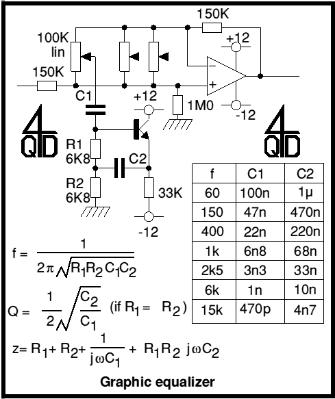
Audio graphic equalizers are very common as commercial products (for Hi-fi, car audio and stage use) but circuits for them are very rarely published. I didn't design this one but it's really very simple. The details shown are...
The circuit design utilizes a VHF amplifier configured to operate within the frequency range of 88 to 108 MHz, specifically for Band 2 radio applications. The VHF amplifier circuit is designed to enhance weak radio frequency signals in the specified...
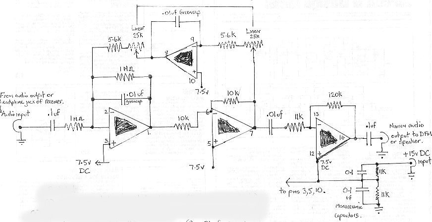
The audio bandpass filter described is beneficial for amplifying and filtering weak AM TV video carriers. For instance, a digital frequency audio multimeter (DFM) may lack sufficient input sensitivity for measuring extremely weak single sideband (SSB) TV video audio...
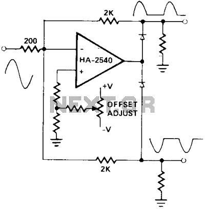
A circuit utilizing either the HA-2539 or HA-2540 in conjunction with two low-capacitance switching diodes can effectively separate signals exceeding 10 MHz. This configuration is particularly beneficial for applications such as full-wave rectification, AM detection, or synchronization generation. The described...
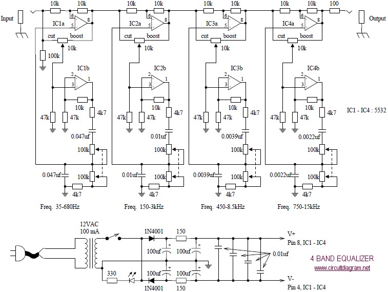
The following diagram illustrates a four-band blaster circuit. This blaster is utilized to enhance sound fidelity, emphasize specific instruments, eliminate unwanted noise, or create entirely new and distinct timbres. The four-band blaster circuit is designed to manipulate audio signals across...