
4 Band Equalizer schematic diagram

The four-band blaster circuit is designed to manipulate audio signals across four distinct frequency bands. Typically, these bands are categorized into low, mid-low, mid-high, and high frequencies. Each band is processed through a separate equalization stage, allowing for precise control over the amplitude and tonal characteristics of the audio signal.
The circuit generally consists of the following key components:
1. **Input Stage**: This stage receives the audio signal, which can come from various sources such as musical instruments or microphones. It often includes a buffer amplifier to ensure that the input impedance is high enough to prevent signal loss.
2. **Equalization Stages**: Each of the four bands is processed through its own equalizer, which may utilize active or passive components. Active equalizers typically use operational amplifiers (op-amps) to achieve greater control over the gain and bandwidth of each band. The design may include adjustable potentiometers for tuning the gain of each band, allowing users to tailor the sound to their preferences.
3. **Mixing Stage**: After processing, the signals from each band are mixed together. This stage may include additional circuitry to maintain a balanced output level and to prevent distortion.
4. **Output Stage**: The final output stage may include a power amplifier or a simple buffer to drive the output signal to the desired load, such as speakers or recording equipment. This stage ensures that the output maintains fidelity and clarity, preserving the enhancements made during processing.
The four-band blaster circuit is particularly useful in live sound applications and studio settings, where control over frequency response is crucial for achieving high-quality sound. By effectively managing the tonal balance, it allows sound engineers and musicians to craft their desired audio experience, whether for live performances or recorded tracks.The afterward diagram is the four bandage blaster circuit. Blaster is about acclimated to advance the allegiance of sound, to accent assertive instruments, to abolish causeless noises, or to actualize absolutely new and altered timbres 🔗 External reference
Related Circuits
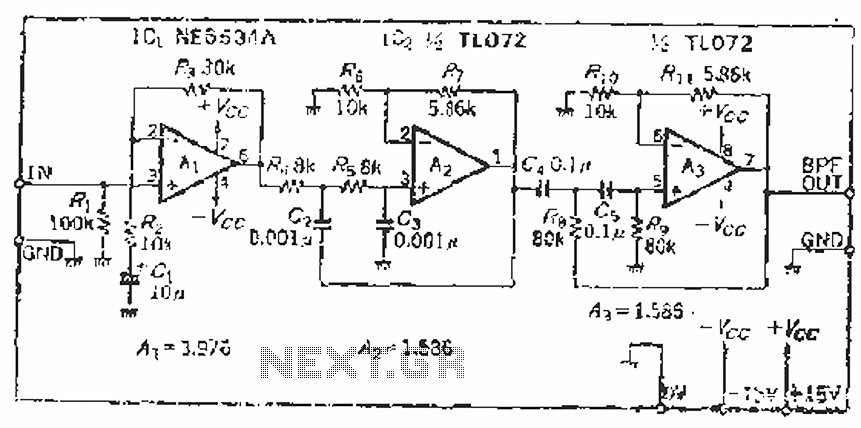
The filter incorporates a zoom function, with a front satin amplifier magnification calculated as d = 10/2.515 = 3.97, which results in a total beam compared to a 10 times magnification. The low-pass filter parameters are specified as a...
The cumulative timer circuit comprises resistor R1 and an internal crystal oscillator, represented in a chart. Resistors R1 and R2 are metal film types, while resistors R3 to R5 are rated at 1/8W and also of the metal film...

This circuit is designed for tone control utilizing a three-band equalizer. It is based on the LF351 single-chip operational amplifiers. The circuit features three adjustable ranges: bass, mid, and treble controls. The equalizer allows for approximately +/-20 dB of...
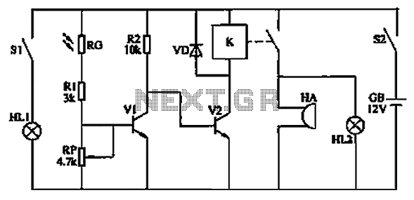
The circuit functions as a reminder system utilizing a photodetector amplifier circuit along with a sound and light alarm circuit, as illustrated in Figure 1. The photodetector amplifier circuit consists of a pilot light (HL1), a light switch (S1),...
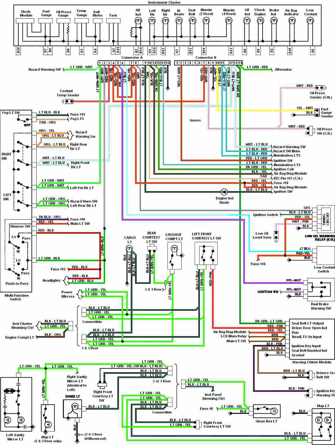
Automotive diagram for the instrument cluster of the 1987-1993 Ford Mustang (Third Generation). The instrument cluster for the 1987-1993 Ford Mustang serves as a critical interface for the driver, providing essential information about the vehicle's operational status. This cluster typically...
Once again, this is a project designed by David Sayles. The input can be from a longwire or a loop antenna. The unit covers MW and Sw to 30MHz. This project involves a versatile antenna interface designed to accommodate...