
6-Band Graphic Equalizer

The EQ-2 circuit is designed for audio frequency control, specifically for equalizing the frequency response in audio systems. The six bands of regulation allow for a more precise adjustment of the sound profile, providing a wide range of tonal options. The potentiometers RV1-6, as the primary control elements, are responsible for adjusting the gain of each frequency band. The use of Faders, instead of simple potentiometers, enhances the visual feedback for the user, making it easier to identify and adjust the levels of each band.
When the potentiometer is in the middle position, it indicates a flat response, meaning there is no gain or loss in the signal level. However, when moved to the terminal, it can either boost the signal by 15 decibels or cut it off by the same amount, offering a significant range of amplification or attenuation for each band.
The circuit is designed for stereo operation, which means it will be used in pairs for left and right channels to maintain the stereo effect. This dual-channel operation is typical for audio systems to ensure that the sound output is balanced and equalized across both speakers.
In summary, the EQ-2 circuit is a sophisticated audio control system that allows for fine-tuning of sound frequencies through its 6-band regulation, adjustable via potentiometers or Faders. Its design is suitable for stereo operation, ensuring balanced sound output across both channels.The EQ-2 it is a circuit of graphic equalizer 6 band of regulation. Each band is regulated from the potesometers RV1-6, that are, for better optical indicate of regulations, Fader. This does not mean that we cannot him replace with simply potesometer. In the center of regulation potesometer, the gain is null (flat), but in terminal has +/- 15 db, boost or cutting off, respectively.
For stereo operation, it will be supposed two times. 🔗 External reference
Related Circuits
This simple equalizer circuit utilizes a single operational amplifier (op-amp) to provide three distinct frequency ranges: low frequency, mid frequency, and high frequency. With the specified component values, the circuit is capable of delivering an approximate gain of +/-20dB...
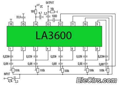
Circuit LA3600 5 Band Equalizer Circuit Schematics. One type of tone control in audio electronics is the graphic equalizer. Graphic equalizers can be categorized into two types: bar and other configurations. The LA3600 circuit is a 5-band graphic equalizer designed...
This complete high quality, low noise 5-BAND GRAPHIC EQUALIZER circuit is based around Monolithic Linear integrated circuit LA3600 manufactured by SANYO. This circuit is very easy to build and has good Quality. You can use it with Portable component...
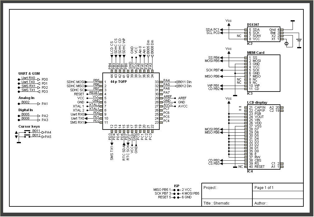
AVRtools features an intuitive graphical user interface and utilizes predefined function blocks. It provides a wide array of basic functions, including timers, counters, logic operations, and analog signal processing. Additionally, it includes function blocks for sending SMS messages over...
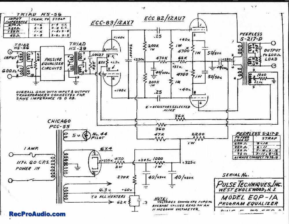
This project closely replicates the vintage Pultec EQP-1a equalizer. It is constructed from the original Pulse Techniques Pultec schematic, with the layout adapted for modern replacement components such as filter capacitors and transformers. The total parts cost is approximately...

The circuit of a graphic equalizer features ten adjustable potentiometers, each affecting a specific range of frequencies. The central frequency of each potentiometer is spaced one octave apart from the central frequencies of the adjacent ranges. Each unit utilizes...