
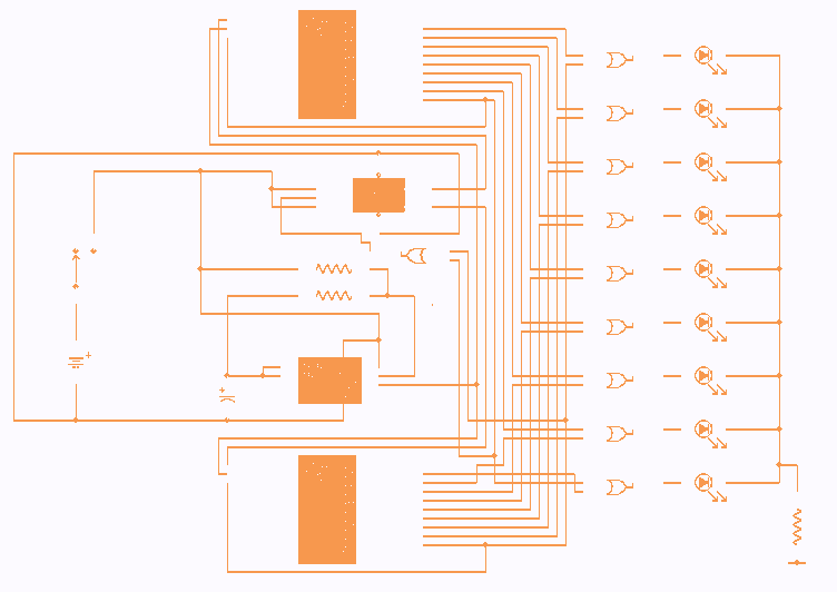
10 Led Chaser

Part List
R1= 100 ohms
D1-10= LED
IC4= 7442 for output 16mA
R2= 220 ohms
IC1= 7400
IC4= 7445 for output 80mA
TR1= 470 ohms trimmer
IC2= 74193
C1= 1000uF 16V
IC3= 7404
The circuit functions as a visual display mechanism, simulating the motion of a ball through the sequential illumination of LEDs. The core of the operation is based on a synchronous up/down counter (IC2) that counts in both directions depending on the state of the flip-flop formed by gates IC1A-B. The counting direction is determined by the activation of the limit LEDs (D1 and D10), which signal the counter to reverse its counting direction upon reaching either end of the LED array.
The clock signal generated by the inverters (IC3A-B) is crucial for controlling the timing of the LED activation. The frequency of this clock signal can be fine-tuned using the trimmer resistor (TR1) or by adjusting the capacitance of C1. This flexibility allows for a range of visual effects, enabling the user to customize the speed of the LED sequence to suit specific applications or aesthetic preferences.
The BCD decoder (IC4) serves as the interface between the counter and the LEDs, translating the binary count into a format suitable for driving the individual LEDs. The choice between using the 7442 or 7445 decoder ICs allows for different output current capabilities, providing options for driving the LEDs based on their specific power requirements.
Overall, this circuit exemplifies a simple yet effective method for creating an engaging visual display through the use of basic digital components, making it suitable for educational purposes, decorative applications, or as part of a larger electronic project.This circuit us gives the sense of movement of ball up down, after the LED turn on successively the one afterwards the other. As soon as it reaches in the one or in the other end it makes again the opposite movement to behind. As clock are used two inverters IC3A-B, the third IC3C are have role buffer. The R1, TR1, C1, determine the frequency, hence also the speeds of movement. We can adjust the TR1 in order to we achieve the change of speed or we change the price of C1, proportionally the speed that we want to achieve.
The signal of clock passes from the IC1C-D, in the entries increasing or decreased enumeration (synchronous up/down counter), the IC2. The increasing or clipping enumeration is selected by the gates ICA-B, that is connected so as to takes shape a set/reset flip-flop. The flip-flop this changes situation, when they turn on LED D1 and D10, that is found in the limits of bar, forcing the circuit to work to the opposite direction.
This circle is continued, as long as it is in supply the circuit. The four exits of IC2, drive the entries of IC4, that are a decoder BCD, 4 lines in 10. The outputs of IC4, connect with LED D1-10.Every from the 10 exits remains in situation [H], while a situation [L] travels from a end of LED's, in the other. When one from output pins of IC4 becomes [ L ] then turns on also the corresponding LED. In the place of IC4 we have two choices, as long as report completed that we can place: 1) with the 7442 us it gives until 16mA, in his exits and 2) the 7445 that it gives 80mA.
Part List R1= 100 ohms D1-10= LED IC4= 7442 for out 16mA R2= 220 ohms IC1= 7400 IC4= 7445 for out 80mA TR1= 470 ohms trimmer IC2= 74193 C1= 1000uF 16V IC3= 7404 🔗 External reference
Related Circuits
As a keen cyclist I am always looking for ways to be seen at night. I wanted something that was a novelty and would catch the motorists eye. So looking around at my fellow cyclists rear lights, I came...
High brightness (HB) and super HB LEDs are utilized in LCD TFT backlighting for high-end televisions, industrial lighting, and projectors. A notable application is in instrument panel backlighting, interior lighting, and brake lights of various vehicles. Luxury automobile manufacturers...
The rotary switch is available for $5.00USD as of 2003 from DigiKey under part number EG1951-ND or EG1952-ND. It is a real pain to operate this circuit without a proper switch. You can put multiple 4017 ring counters in...
The yellow LEDs are on a small PCB, which are easy to remove. On the PCB there are 3 yellow LEDs and 4 diodes. Pictures of the PCB can be seen here: Top-side - Bottom-side. The schematic is as...
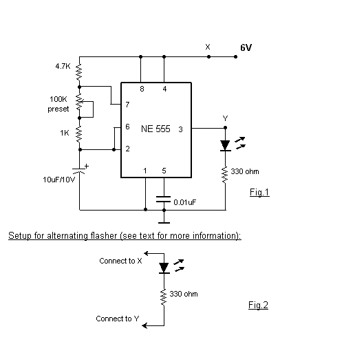
This is a very basic circuit for flashing one or more LEDs and also to alternately flash one or more LEDs. It uses a 555 timer setup as an astable multivibrator with a variable frequency. With the preset at...

A high-quality QRP transmitter, named NEXUS 6, is designed to explore issues related to extremely narrow bandwidth communication. This device is not merely a simplified version of a QRP transmitter; it aims to create a cost-effective system that can...