
Using white LEDs

The described circuit involves a small printed circuit board (PCB) equipped with three yellow light-emitting diodes (LEDs) and four diodes. The design allows for easy removal of the components, facilitating modifications and replacements. The initial configuration includes three yellow LEDs connected in parallel, with the four diodes arranged in series.
To modify the circuit, the three yellow LEDs and three of the normal diodes are removed. It is noted that removing only the outer two diodes leaves the center diode unconnected, which can be beneficial for maintaining circuit integrity while making changes.
The circuit design incorporates a zener diode and a resistor. The recommended values for the resistor are 470 Ohms with a power rating of 5 Watts, while a zener voltage of 3.3 Volts is suggested to ensure proper voltage regulation. The resistor limits the current flowing through the zener diode, protecting it from excessive current that could lead to failure.
The design allows flexibility in the number of normal diodes used in series; however, accommodating four or five diodes may present physical fitting challenges on the PCB.
For the final modification, the yellow LEDs are replaced with white LEDs, and the normal diodes are substituted with a zener diode. The zener diode serves to regulate voltage for the white LEDs, ensuring they operate within their specified voltage range. The circuit should be connected according to the provided schematic to ensure proper functionality and performance of the white LEDs. This configuration allows for effective light emission while maintaining circuit stability and reliability.The yellow LEDs are on a small PCB, which are easy to remove. On the PCB there is 3 yellow LEDs and 4 diodes. Pictures of the PCB can be seen here : Top-side - Bottom-side. The schematic is as follows : You now remove the 3 LEDs and the 3 normal diodes (the ones who are in series). I actually only removed the outer 2 as the remainder is then left unconnected. The value of zener diode and the resistor, can be changed, but I found a value of 470 Ohm/5W for the resistor and 3,3 Volt for the zener to be OK.
You can also put 4 or 5 normal diodes in series instead of the standard 3 - but it may be hard to fit them. Now you place a zener diode instead of the normal diodes, and the white LEDs instead of the yellow LEDs.
It should be connected as this schematic describes : 🔗 External reference
Related Circuits
The 2N3819 is an n-channel JFET specifically designed for RF and mixer applications, offering very low noise, minimal distortion, and excellent high-frequency gain. Creating a PCB can be accomplished in a few straightforward steps. Begin by using PCB design...
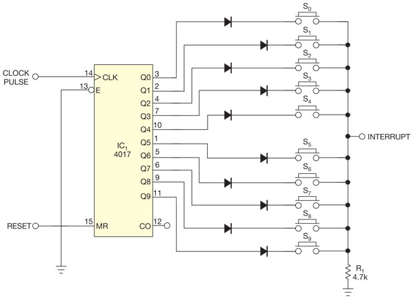
There are several methods to read multiple switch inputs using a reduced number of microcontroller unit (MCU) pins. One approach involves using an analog MCU pin to read multiple switches by assigning a unique voltage to each switch through...
This circuit can generate a voltage of 15V. In this circuit, the LM340 input voltage must remain within the limits specified in the data sheet. If the device is operated above the absolute maximum input voltage rating, two failure...
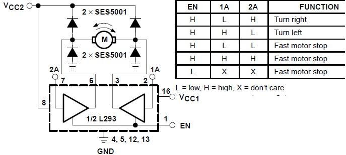
The L293 is designed to provide bidirectional drive currents of up to 1 A at voltages ranging from 4.5 V to 36 V. The L293D variant is capable of delivering bidirectional drive currents of up to 600 mA at...
A novice in circuit creation is utilizing a 12V battery regulated to 2mA with an LM334Z current regulator. Documentation for the current regulator is available. The LM334Z is a versatile current regulator that can be used in various applications requiring...
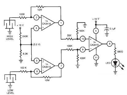
This liquid level sensor electronic circuit diagram utilizes a common CA3410 operational amplifier integrated circuit (IC). The sensor employs two plate sensors (or probes), one designated for detecting high liquid levels and the other for low liquid levels. If...